EasyManuals Logo

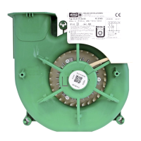
Helios MultiVent MV EC Series User Manual

Helios MultiVent MV EC Series
To Next Page IconTo Next Page
To Previous Page IconTo Previous Page
Page #36 background imageLoading...
Page #36 background image
EN EN
MultiVent
®
MV EC
Installation and Operating Instructions
12
SS-1195
MV EC 315
Alternating current,
1~, 230 V, 50 Hz
with PU/A 10
250 V
3A
N
L
S2
S1
P0
PI
P10
+10V
0-10 V
GND
P1
MV EC 315 + PU/A 10
85460 001 SS-1195 08.06.20 S.2
R1
R2
3
2
4
PU/A 10
1
Potentiometer min.
rotational speed
7
6
5
LED 1
LED 2
S 1
R 1
Art.Nr. 1734/1735
43L2 N1
lid
1)
2)
3)
250 V
3A
N
L
S2
S1
P0
PI
P10
+10V
0-10 V
GND
P1
MV EC 315 connection
L N
R1
R2
43L2 N1
lid
1)
2)
3)
4) with setpoint setting and without fault signal
5) without setpoint setting or with fault signal
LED display logic
terminal 6
10 V
10 V
0 V
0 V
terminal 7
0 V
10 V
10 V
0 V
LED display
red (1)
green (2)
Fan without mains supply
Fan with mains supply,
fan rotates
4)
relay contact R1-R2
open
closed
fan status
Fan with mains supply,
Fan stopped
5)
open
L N
10k
0-10V signal from e.g.
PU/A 10 Art.Nr. 1734/1735
or EUR EC Art.Nr. 1347
Potentiometer or rather
Isolation switch
to be provided by
customer
Isolation switch
to be provided by
customer
1) device type (SW1)
1
off
on
2 3 4
1
off
on
2 3 4
1
off
on
2 3 4
1
off
on
2 3 4
1
off
on
2 3 4
MV EC 125
MV EC 160
MV EC 200
MV EC 250
MV EC 315
2) factory setting
(0-10V control voltage)
3) factory setting
1
off
on
2 3 4
MV EC 100
1
off
on
2 3 4
MV EC 150
Fig�25

Questions and Answers:

Question and Answer IconNeed help?

Do you have a question about the Helios MultiVent MV EC Series and is the answer not in the manual?

Helios MultiVent MV EC Series Specifications

General IconGeneral
BrandHelios
ModelMultiVent MV EC Series
CategoryFan
LanguageEnglish

Related product manuals