FR FR
MultiVent
®
– MV EC
Notice de montage et d’utilisation
11
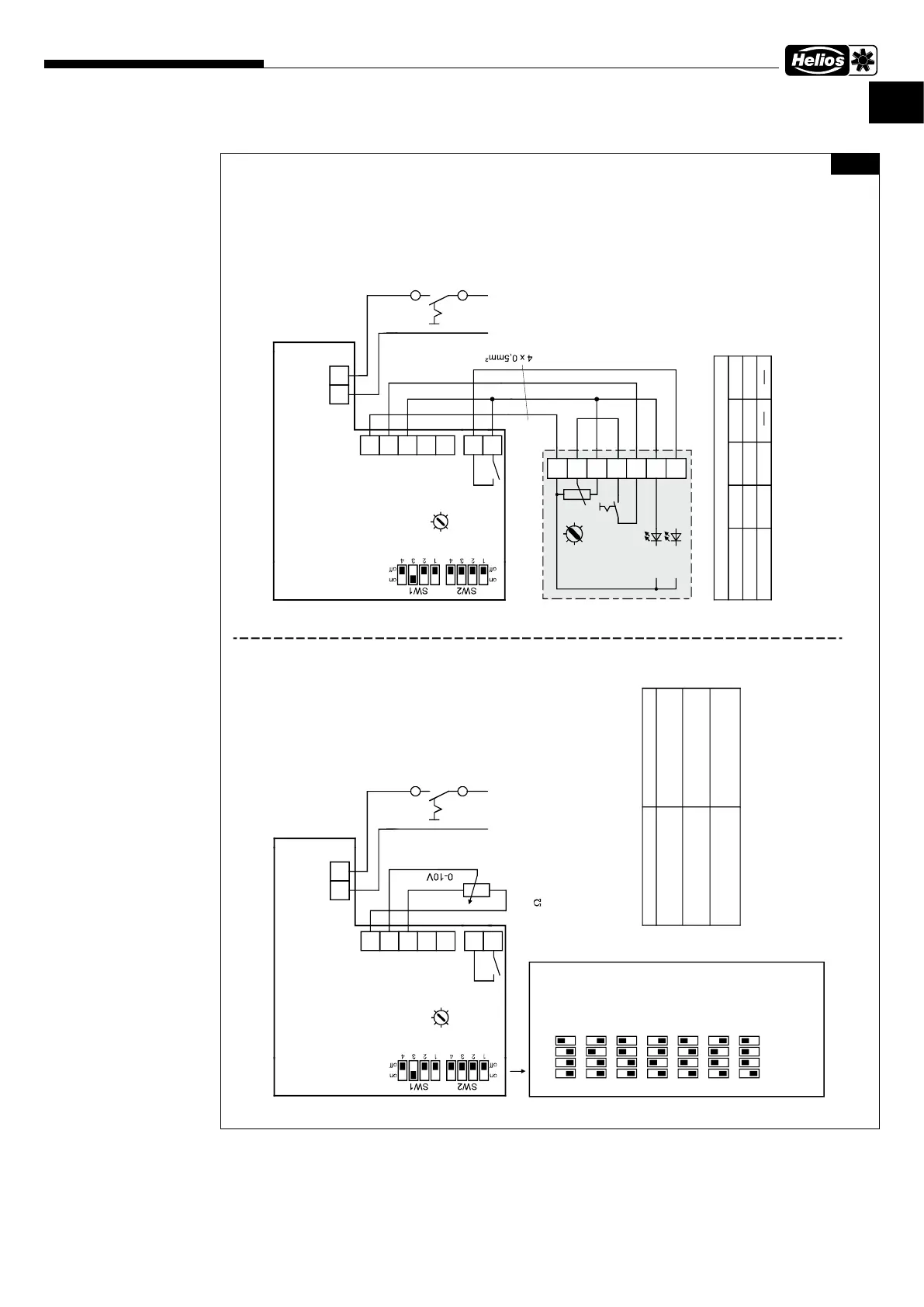
6�2�1 Schémas de raccordement standard avec PU/A 10
SS-1194
MV EC 100
MV EC 125
MV EC 150
MV EC 160
MV EC 200
MV EC 250
Courant alternatif,
Monophasé, 230V, 50Hz
avec PU/A 10
250 V
3A
NL
S2
S1
P0
PI
P10
+10V
0-10 V
GND
P1
MV EC 100 - 250 + PU/A 10
85459 001 SS-1194 08.06.20 S.3
R1
R2
3
2
4
PU/A 10
1
potentiomètre
réglage de la
vitesse mini
7
6
5
LED 1
LED 2
S 1
R 1
Art.Nr. 1734/1735
1)
2)
3)
250 V
3A
NL
S2
S1
P0
PI
P10
+10V
0-10 V
GND
P1
MV EC 100 - 250 raccordement
LN
R1
R2
1)
2)
3)
Logique de l'affichage LED
Borne 6
10 V
10 V
0 V
0 V
Borne 7
0 V
10 V
10 V
0 V
Affichage LED
rouge (1)
vert (2)
10k
0-10V signal par ex.
de PU/A 10 Art.Nr. 1734/1735
ou EUR EC Art.Nr. 1347
Potentiomètre resp.
LN
1) Dispositifs (SW1)
1
off
on
2 3 4
1
off
on
2 3 4
1
off
on
2 3 4
1
off
on
2 3 4
1
off
on
2 3 4
MV EC 125
MV EC 160
MV EC 200
MV EC 250
MV EC 315
2) Réglage d'usine
(Tension de 0-10V)
3) Réglage d'usine
4) avec réglage du point de consigne et sans alerte de défaut
5) sans réglage du point de consigne ou avec alerte de défaut
Ventilateur hors tension
Ventilateur sous tension,
ventilateur rotatif
4)
contact de relais R1-R2
ouvert
fermé
statut de ventilateur
Ventilateur sous tension,
ventilateur s'arrête
5)
ouvert
interrupteur de
(fourniture client) resp.
interrupteur de
(fourniture client) resp.
1
off
on
2 3 4
MV EC 100
1
off
on
2 3 4
MV EC 150
Fig�24
 Loading...