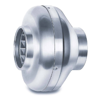
Radial-Rohrventilatoren Serie RR...
Centrifugal ‘In-Line’ Duct Fans serie RR...
Ventilateurs Centrifuges série RR...
4
ACHTUNG: Die volle Ventilatorleistung wird nur
e
rreicht, wenn freie An- und Abströmung gege-
ben ist. Für ausreichende Motorkühlung muss si-
c
hergestellt sein, dass eine Mindest-Luftströmungs-
fläche von 20 % des Ventilatorquerschnittes gegeben
ist.
KONDENSWASSERBILDUNG
B
ei periodischem Betrieb, bei feuchten und warmen
Fördermitteln und durch Temperaturschwankungen
(
Aussetzbetrieb) entsteht innerhalb des Motors Kon-
densat, dessen Abfluß sichergestellt werden muss.
F
alls sich in Rohrleitung u. Ventilatorgehäuse Kon-
densat bilden kann, sind entsprechende Vorkehrun-
g
en (Wassersack, Drainageleitung) bei der Installation
zu treffen. Der Motor darf keinesfalls mit Wasser be-
a
ufschlagt werden.
FUNKTIONSSICHERHEIT – NOTBETRIEB
Bei Einsatz des Ventilators in wichtiger versorgungs-
technischer Funktion, ist die Anlage so zu konzipie-
r
en, dass bei Ventilator-Ausfall automatisch ein Not-
betrieb garantiert ist. Geeignete Lösungen sind z.B.
P
arallelbetrieb von zwei leistungsschwächeren Gerä-
ten mit getrenntem Stromkreis, stand-by Ventilator,
A
larmeinrichtungen und Notlüftungssysteme.
MOTORSCHUTZ
Alle Typen sind, mit der Wicklung in Reihe verdrahteten
Thermokontakten, ausgerüstet. Schutz durch selbst-
tätiges auslösen – nach erfolgter Abkühlung selbsttä-
tiges Widereinschalten.
ACHTUNG: Bei häufigem Auslösen des Thermo-
kontakts (Stillstand) muss Ventilator überprüft
werden. Vor Arbeiten am Ventilator diesen allpo-
lig vom Netz trennen (siehe „Elektrischer
Anschluss“) da Thermokontakt evtl. selbsttätig
einschaltet.
INBETRIEBNAHME
Folgende Kontrollarbeiten sind auszuführen:
• Bestimmungsgemäßen Einsatz des Ventilators
überprüfen
• Netzspannung mit Leistungsschildangabe ver-
gleichen
• Ventilator auf solide Befestigung prüfen
• Alle Teile, insbes. Schrauben, Muttern, Schutz-
gitter auf festen Sitz überprüfen
• Freilauf des Laufrades prüfen
• Stromaufnahme mit Leistungsschildangabe ver-
gleichen
• Schutzleiteranschluss prüfen
• Abdichtung des Anschlusskabels und festen
Klemmsitz der Adern prüfen
• Inbetriebnahme darf nur erfolgen, wenn der Be-
rührungsschutz des Laufrades sichergestellt ist.
GERÄUSCHPEGEL
Die im Katalog genannten Geräuschwerte können im
Einbaufall erheblich abweichen, da der Schalldruck-
pegel vom Absorbtionsvermögen des Raumes, der
Einbausituation u.a. Faktoren abhängig ist. Geräusch-
minderungen können durch den Einatz von Schall-
dämpfern und durch Drehzahlreduzierung (Regelung)
erzielt werden.
CAUTION: Maximum fan performance is achie-
v
ed only under free inlet and discharge conditi-
ons.
CONDENSATION
If the fan is used intermittently, especially in a humid
a
nd warm environment, or if variations in temperatu-
re occur, condensation may build up in the motor and
d
raining off must be ensured.
In case of condensation in the ducting and fan casing
a
ppropriate measures must be taken during installation
(condensation trap). Under no circumstances must
t
he motor come into contact with condensation water.
In case of damage through incorrect installation
H
elios is released from all guarantee claims.
O
PERATIONAL SAFETY – EMERGENCY
OPERATION
If the fan is installed for important applications in ca-
se of a fan breakdown a guaranteed emergency ope-
ration must be ensured. Suitable options are: parallel
o
peration of 2 lower performance fans with separate
power supplies, a standby unit, or an alarm system.
MOTOR PROTECTION
A
ll models have thermal contacts wired in series with
t
he motor windings which automatically restart after
cooling down.
NOTE: Frequent thermal cut-outs require in-
spection of the motor. Isolate fan from mains be-
fore inspection (see ”Electrical connection”) as
the thermal cut-out could restart the fan automa-
tically.
PREPARING FOR OPERATION
The following checks must be carried out:
• check that the fan is operated according to its in-
tended purpose
• check that mains supply conforms with the figures
on the rating plate
• check that fan is securely mounted
• check that all parts, especially screws, nuts and
grille are tightly fitted
• check free rotation of the impeller
• compare current drawn with data on the rating pla-
te
• check that the appliance is earthed
• check that cable entry is sealed
• check that connection of terminals is tight
• operate only if the impeller is sufficiently protected
against accidental contact.
SOUND LEVELS
The sound levels of the installation can differ consi-
derably from those stated in the catalogue as the
sound pressure level depends on the absorption ca-
pacity of the room, the type of installation etc.
Reduction in noise levels can be achieved through at-
tenuators and/or speed control.
FORMATION DE CONDENSATS
E
n cas de fonctionnement intermittent, de transport de
fluides humides ou chauds, de variations de tempé-
r
ature, il se forme à l'intérieur du moteur un condensat
(condensation d'eau) qui doit absolument être évacué.
S
'il y a des risques de condensation dans la gaine et
dans l'enveloppe du ventilateur, il est nécessaire de
p
révoir une boucle de condensats avec évacuation.
L'eau ne doit en aucun cas pénétrer dans le moteur.
Le non-respect de la règle d'évacuation des conden-
s
ats entraîne la perte de la garantie.
S
ÉCURITÉ DE FONCTIONNEMENT -
SYSTÈME DE SECOURS
L
orsque le ventilateur a une fonction technique déter-
minante, l'installation doit être conçue de sorte qu'un
s
ystème de secours soit automatiquement assuré en
cas de défaillance du ventilateur. Les solutions suivantes
p
euvent être envisagées: fonctionnement simultané
de deux appareils de performances inférieures sur
deux enceintes séparées, ventilateur en stand-by,
dispositifs d'alarme, système d'aération de secours.
PROTECTION DU MOTEUR
Tous les types sont équipés de thermocontacts bran-
c
hés en série incorporés dans le bobinage.
P
rotection par déclenchement automatique - enclen-
chement automatique après refroidissement.
ATTENTION: En cas de coupure fréquente des
thermocontacts (arrêt) le ventilateur doit être vé-
rifié. Avant toute intervention, déconnecter l'ali-
mentation électrique (voir "Branchement électri-
que") pour éviter toute mise en marche automati-
que intempestive.
MISE EN MARCHE
Les opérations de contrôle suivantes sont à effectuer:
• contrôler si l'installation du ventilateur est conforme
aux prescriptions
• vérifier si la tension d'alimentation correspond à
celle indiquée sur la plaque signalétique
• contrôler la fixation du ventilateur
• vérifier le serrage de toutes les pièces, en particulier
celui des vis, écrous, grilles de protection
• contrôler la libre rotation de l'hélice
• comparer l'ampérage absorbé avec l'indication de
la plaque signalétique
• vérifier le raccordement entre câble et prise de ter-
re
• contrôler l'isolation du câble de raccordement et le
serrage de toutes les cosses
• n'effectuer la mise en route qu'à condition que
l'hélice soit protégée de tout contact
NIVEAU SONORE
Lors d'une installation, le niveau sonore peut varier
substantiellement par rapport aux spectres sonores
indiqués dans le catalogue étant donné qu'il dépend,
entre autres, du pouvoir d'absorption du local et de
la situation de l'installation. Une réduction du niveau
sonore peut être obtenue par l'utilisation de silen-
cieux et par une réduction de la vitesse (régulation).
 Loading...