DJ Monitor 5
6/10 – User manual
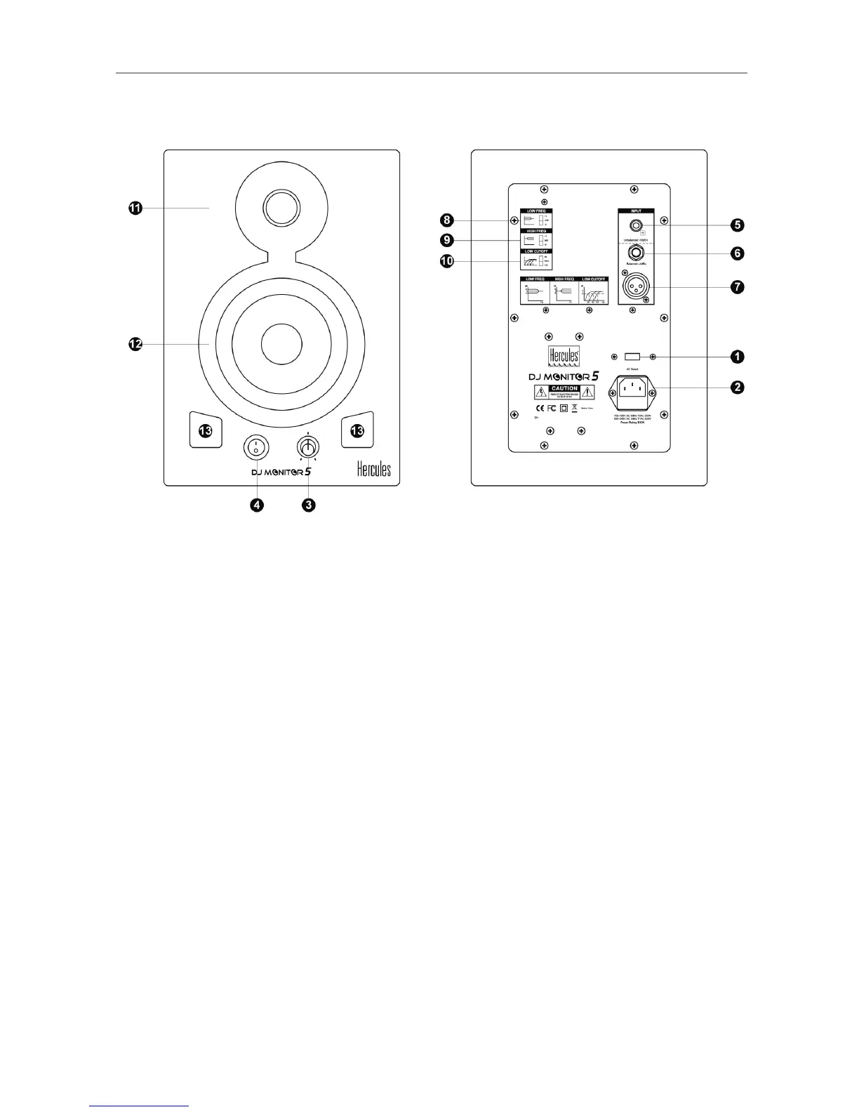
2.2. Overview of front and rear panels
Two possible positions: 230 V for a 220-240 V
power supply, or 115 V for a 110-120 V power
supply.
2. Power connector
Connect the power cable here.
3. Volume knob and power LED
The LED lights up when the ON/OFF button is set to
ON.
4. ON/OFF button
When your audio system (
speakers) is connected, power on the DJ Monitor 5
speakers last, and power off the DJ Monitor 5
speakers before powering off your audio system.
5. RCA (Cinch) connector for main input
6. TRS connector for balanced input
6.35 mm jack type connector.
7. XLR connector for balanced input
The most frequently used connector with
professional equipment and installations, thanks to
its electrical and mechanical reliability.
Lets you adjust the level of the low frequency
range. +2 dB: increases the range by 2 dB; 0:
uniform frequency response; -2 dB: decreases
the range by 2 dB.
9. High Freq switch
Lets you adjust the level of the high frequency
range. +2 dB: increases the range by 2 dB; 0:
uniform frequency response; -2 dB: decreases
the range by 2 dB.
10. Low Cutoff switch
Three available cutoff frequencies for the low-
cut filter: 56, 80 and 100 Hz.
11. Tweeter (high frequency driver)
Produces high frequency sounds.
12. Woofer (low frequency driver)
Produces low frequency sounds.
13. Bass reflex ports
Improve the rendering of low frequencies.
 Loading...