Page 5Item 56458
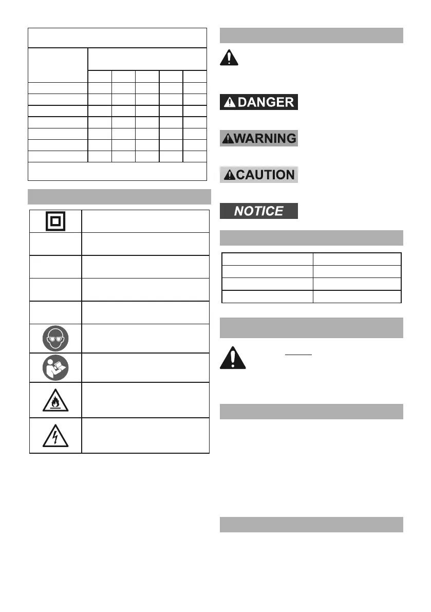
0 – 2.0 18 18 18 18 16
2.1 – 3.4 18 18 18 16 14
3.5 – 5.0 18 18 16 14 12
5.1 – 7.0 18 16 14 12 12
7.1 – 12.0 18 14 12 10 -
12.1 – 16.0 14 12 10 - -
16.1 – 20.0 12 10 - - -
Symbology
Double Insulated
Volts
~
Alternating Current
A
Amperes
n
0
xxxx/min.
No Load Revolutions
per Minute (RPM)
WARNING marking concerning Risk
of Eye Injury. Wear ANSI-approved
safety goggles with side shields.
Read the manual before
set-up and/or use.
WARNING marking
concerning Risk of Fire.
Do not cover ventilation ducts.
Keep flammable objects away.
WARNING marking concerning
Risk of Electric Shock.
Properly connect power cord
to appropriate outlet.
Warning Symbols and Definitions
Specifications
Electrical Rating 120VAC / 60Hz / 3A
No Load Speed 8000 - 13,000 OPM
Paper Attachment Hook and Loop
Pad Size 5″ (127 mm)
SETUP - BEFORE USE:
Assembly
1. Slide the onto the Dust Chute at the back
of the Sander. Push the Dust Box fully onto the Dust
Chute using firm pressure. Press the
and release. Lock the Tab Hooks into the Tab Slots.
2. The collection of the dust will only work if the
sandpaper has holes that line up with the 8 dust
collection holes in the Backing Pad. There are
3 other holes in the Backing Pad for the Screws
that attach the Backing Pad to the Sander.
Power Supply Requirements
120VAC, 60Hz
 Loading...