17
G
B
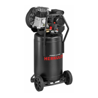
2. FEATURES (Pic. 1)
A. I/O Switch (ON/OFF): The I/O switch is the activation mechanism
that is used to start and stop the compressor. When the switch is
“On”, the motor and pump will compress air until tank pressure
reaches the upper limit of the factory set operating pressure.
When tank pressure falls below the factory set “cut in” pressure,
the compressor will again automatically start to compress air.
B. Regulated Pressure Gauge: The regulated pressure gauge
indicates the amount of pressure that is allowed into the discharge
line according to the setting of the regulator.
C. Regulator Knob: The regulator knob is used to adjust the air
pressure that is available at the discharge line. The discharge
air pressure is increased by turning the knob clockwise and
decreased by turning the knob counter clockwise.
D. Drain Valve: Ball style valve that drains moisture from the tank
when opened.
E. Quick Coupler: The quick coupler is used to connect the airline
to your tool.
F. Safety valve: The safety valve is set to avoid over-pressurization
of the air tanks. This valve is factory pre-set and will not function
unless tank pressure reaches this pressure. Do not attempt to
adjust or eliminate this safety device.
Any adjustments to this valve could cause serious injury. If this
device requires service or maintenance, see an Authorized
Service Center.
G. Handle for lifting/moving.
H. Rubber foot.
I. Intake air lter.
J. Pressure gauge: It indicates the tank pressure.
3. SCOPE OF USE
The compressor is designed for generating compressed air for tools
operated by compressed air.
Please note that our equipment has not been designed for use
in commercial, trade or industrial applications. Our warranty will
be voided if the machine is used in commercial, trade or industrial
businesses or for equivalent purposes.
The machine is to be used only for its prescribed purpose. Any other
use is deemed to be a case of misuse. The user/operator and not
the manufacturer will be liable for any damage or injuries of any kind
caused as a result of this.
4. ELECTRICAL GROUNDING INSTRUCTIONS
The compressor is equipped with a mains cable with shock-proof
plug. Insert the plug of the electric cable in a socket of suitable shape,
voltage and frequency complying with current regulations. Before you
use the machine, make sure that the mains voltage complies with the
specications on the rating plate. Make sure that the ON/OFF switch is
not in the I (ON) position. Long supply cables, extensions, cable reels
etc. cause a drop in voltage and can impede motor start-up. In the
case of low temperatures below +5°C, motor start-up is jeopardized
as a result of stiffness.
5. PRE-START PROCEDURES
● Examine the machine for signs of transport damage. Report any
damage immediately to the company which delivered the compressor.
● Verify that the tanks have been drained and are clear of any moisture
or dirt.
● The compressor should be set up near the working consumer.
● Avoid long air lines and long supply lines (extensions).
● Make sure the intake air is dry and dust-free.
● Do not set up the compressor in damp or wet rooms.
● The compressor may only be used in suitable rooms (with good
ventilation and an ambient temperature from +5°C to +40°C). There
must be no dust, acids, vapours, explosive gases or inammable
gases in the room.
● The compressor is designed to be used in dry rooms. It is prohibited
to use the compressor in areas where work is conducted with
sprayed water.
5.1 Fitting the air lter
Remove the transportation stop with a screwdriver or similar and
screw the air lter (ref. I) securely to the equipment (Fig. 2a-2b).
If supplied, insert the suction tube inside the lter cover (Fig. 2c).
5.2 Assembling the quick coupler (if not already
assembled)
Tighten the quick coupler for regulated pressure to the coupling on the
outlet as shown in gures 4a and 4b.
6. OPERATING INSTRUCTIONS
6.1 I/O switch (ON/OFF) (ref. A)
6.1.1 Fig. 1a, Fig. 1b
To switch on the equipment set the On/Off switch (ref. A) to position I.
Move the On/Off switch (ref. A) to position O to switch off the
equipment.
Warning!
After switching off the compressor, you must wait three seconds
before switching on the machine again.
6.1.2 Fig. 1c
To switch on the compressor, pull out the red knob (ref. A) to position
I (ON).
To switch off the compressor, press the red knob (ref. A) in again to
position O (OFF).
6.2 Adjusting the pressure
● You can adjust the pressure on the pressure gauge (ref. B) using the
pressure regulator (ref. C).
● The set pressure can be taken from the quicklock coupling (ref. E).
6.3 Setting the pressure switch
The pressure switch is set at the factory.
● When the upper calibration value (set by the manufacturer) has been
reached, the compressor stops.
When air is used, the compressor restarts automatically when the
lower calibration value is reached.
● The compressor continues to operate according to this automatic
cycle until the I/O switch (ON/OFF) is turned.
7. CLEANING AND MAINTENANCE
Warning!
Pull the power plug before doing any cleaning and maintenance
work on the appliance.
Warning!
Wait until the compressor has completely cooled down. Risk of
burns!
Warning!
Always depressurize the tank before carrying out any cleaning
and maintenance work.
7.1 Cleaning
● Keep the safety devices free of dirt and dust as far as possible.
Wipe the equipment with a clean cloth or blow it with compressed
air at low pressure.
● We recommend that you clean the appliance immediately after
you use it.
● Do not use cleaning agents or solvents; these may be aggressive to
the plastic parts in the appliance. Ensure that no water can get into
the interior of the appliance.
● You must disconnect the hose and any spraying tools from the
compressor before cleaning. Do not clean the compressor with water,
solvents or the like.
7.2 Draining tank
The condensation water must be drained off each day by opening the
drain valve (ref. D) (on the bottom of the pressure vessel) (g. 3).
1. Verify that the compressor is turned Off.
2. Holding the handle, tilt the compressor toward the drain valve so
that it’s set in a lower position.