39
for the technician
First firing, regulation and servicing instructions
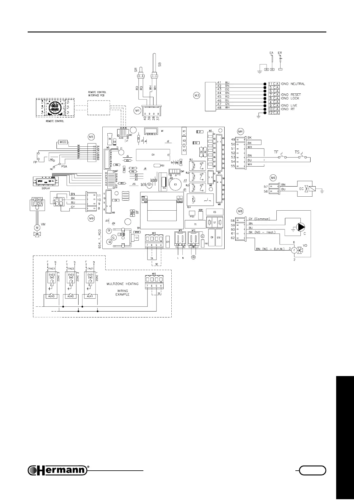
C Pump
EA Ignition electrode
EC Automatic filling device
ER Flame detection electrode
FP Priority flowstat
L Electrical Phase
MOD Modulator
N Electric neutral
PSA Low water pressure switch
(contact “NO” closed = in
pressure)
SB Domestic minitank tempera-
ture sensor
SE External temperature probe
SR Flow temperature sensor
TA Room thermostat
TF Flue thermostat
TS High temperature safety
thermostat
VD Three way valve
VM Motorised mixing valve
EVZ 1/2/3 Electro-valve
zone 1/2/3
AUX 1/2/3 Auxiliary for
EVZ 1/2/3
TAZ 1/2/3 Room thermostat
for zone 1/2/3
C
Note: if optional Remote Control is installed,
multizone heating wiring is different. Refer to
multizone heating diagram supplied with
Remote Control kit.
Colours
abbreviations:
BK Black
BN Brown
BU Blue
GN Green
GNYE Green-Yellow
GY Grey
OG Orange
RD Red
VT Violet
WH White
Electrical diagram
EURA 23-28 E