Please read the Owner’s Manual completely BEFORE operating the unit.
!!!!
When changing cartridge loading resistors, the phono stage should be
unplugged and left off for a minimum of 30 minutes prior to opening the
unit, to insure that hazardous voltages in the power supply have time to
discharge before entering the unit.
Loading resistors should only be changed by technically qualified personnel.
Care needs to be taken during this procedure in order to prevent damage
by static electricity to the field effect transistors in the moving coil input
stage. A grounding wrist strap is highly recommended.
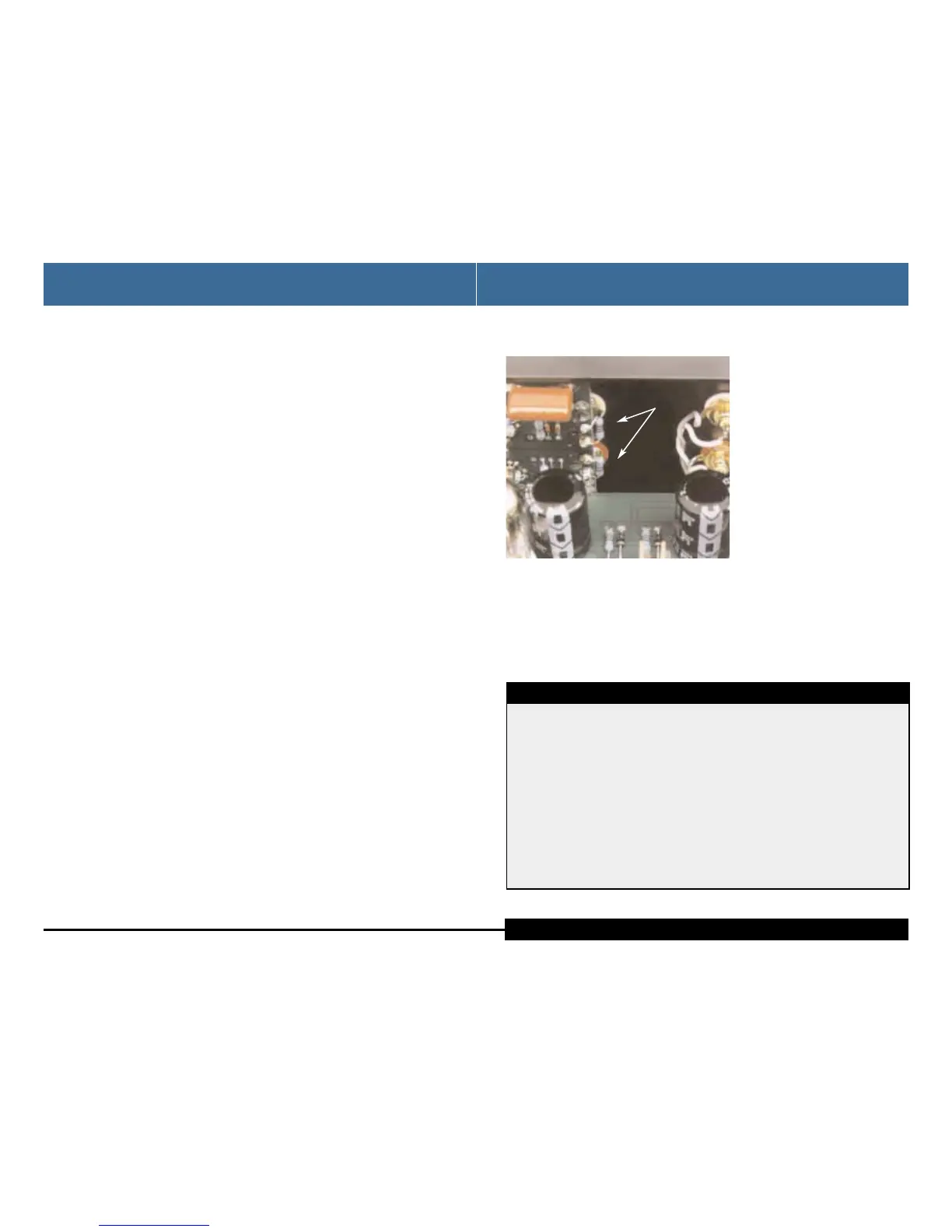
Keep the cartridge load resistor leads short, as shown, to prevent hum pick-
up. Install the grounding lug under the top screw at the rear of the chassis
when reinstalling the cover.
The Herron Phono Preamplifier
is available in different configu-
rations to suit the type of phono
cartridge being used. User adjust-
ments are minimized to simplify
operations. For moving magnet
units, the input impedance is set
at 47,000 ohms in parallel with
100 pF (grid to plate capacitance
of the first 12AX7 multiplied by
the gain—the "Miller Effect").
For moving coil units, optional
internal cartridge loading
resistors can be soldered to the
input connectors, as shown, in parallel with existing 47,000 ohm resistors on
the FET amplifier board. Loading resistor switch contacts would compromise
performance at the small signal levels that are generated by a moving coil car-
tridge. The cartridge loading resistors may be changed by the user, dealer, or
factory, with values appropriate to specific cartridge requirements.
CAUTION CAUTION CAUTION CAUTION CAUTION CAUTION
seven
Optional cartridge loading resistors shown at input
connector terminations of the FET amplifier board.
Cartridge Loading
Cartridge Loading
LOADING
RESISTORS
1. Position the unit in a well-venti-
lated area on a firm, stable
surface, away from equipment
that generates alternating mag-
netic fields such as motors,
transformers, etc. Magnetic fields
of this type can introduce hum
into the signal path.
2. Connect the phono leads to the
phono preamp left-to-left and
right-to-right. Connect the
phono ground bleed wire to the
ground connector of the phono
preamp.
3. Plug the line stage leads into the
output, left-to-left and right-to-
right.
4. Plug the power cord into the
phono preamp. Make sure it is
firmly seated into the IEC socket
prior to inserting the plug into
an AC outlet.
5. Plug the power cord into a 120
volt (U.S. spec units) AC outlet.
6. Power up the unit by switching
on the power switch.
7. Observe the LEDs for the appro-
priate operation (see the Front
Panel Indicators section). Listen
carefully for the click of the auto-
mute engaging the outputs.
8. Once the unit is powered up and
operating, place the line stage
input selector switch to a posi-
tion selecting an unused or
deactivated input.
9. Power up the rest of the system
with the line stage input selector
positioned to select any input
not otherwise in use other than
the phono preamp. With the vol-
ume control of the line stage set
at its lowest position, select the
phono preamp. Gradually
increase the volume control until
a normal listening level is
reached.
six
The operation of the Herron Phono Preamplifier is straightforward. As with any
fine audio component, careful set-up and integration into one’s system is
important for optimum performance, safety, and reliability. Please read through
the following set-up instructions completely prior to operating the unit.
Procedure:
Installation and Operation
Installation and Operation
Owner’s ManualHerron Audio Vacuum Tube Phono Preamplifier
 Loading...