5
3. Using the controller
3.1 Switching the controller on
After connecting the controller to a power source, the controller will switch on in a standby mode. LCD display will become half lit, and the screen will show
the current time. When the controller is in a standby mode, it can be switched on with this button . During the controller's regular mode of
operation, it can be put into standby at any time by pressing this button . In standby, all outputs and the alarm sound signal are switched off.
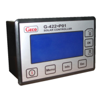
When the controller is switched on, the screen displays an image as presented in picture 2.
Pic. 2. An example of the image appearing on the LCD screen after switching the controller on - main screen.
The number of currently chosen installation type is displayed on the left side, in the top row of the LCD screen. Date and time are displayed on the right
side. Below the date and time row, the installation diagram will be displayed on the left side. Numbers marked in the diagram represent the numbering of
temperature sensors. It is important to remember to install the sensors correctly, in accordance with the description in the diagram. Swapping sensors can
cause an improper functioning of the control system. To the right from the installation diagram, temperatures measured by the sensors are displayed. T1
corresponds to the temperature measured by sensor no. 1, T2 to the temperature measured by sensor no.2, etc. The controller has been designed in such a
way that all four temperature sensors needn't be installed. Only those sensors should be installed which are necessary for controlling the system. When a
sensor necessary for controlling the system is not installed, or becomes damaged, message reading "Err" will appear on the screen next to the sensor's
symbol (as shown in the example in picture 2 for sensors T2 and T4), indicating a lack or damage of the sensor. In such a case, all external devices will be
switched off and the controller will sound a discontinuous alarm sound. When a non-required sensor is not connected to the controller, the controller will not
sound an alarm, and the screen will display horizontal lines where normally temperature is displayed (as shown in picture 2 for the temperature sensor T3).
Below the displayed temperatures, in the right bottom corner of the screen, the momentary collector power, calculated by the controller, is displayed. When
the collector pump is switched off or the return sensor is switched off (usually it is sensor T3), horizontal lines are displayed in place where the power value
is usually displayed. For installation types number 8 and 9, the momentary power calculation option is unavailable.
3.2 Selecting installation type
The controller allows for twelve different solar collector installation configurations. A detailed description of these installation systems is presented in
paragraph 6. A short description of all installation systems is presented in chart 2:
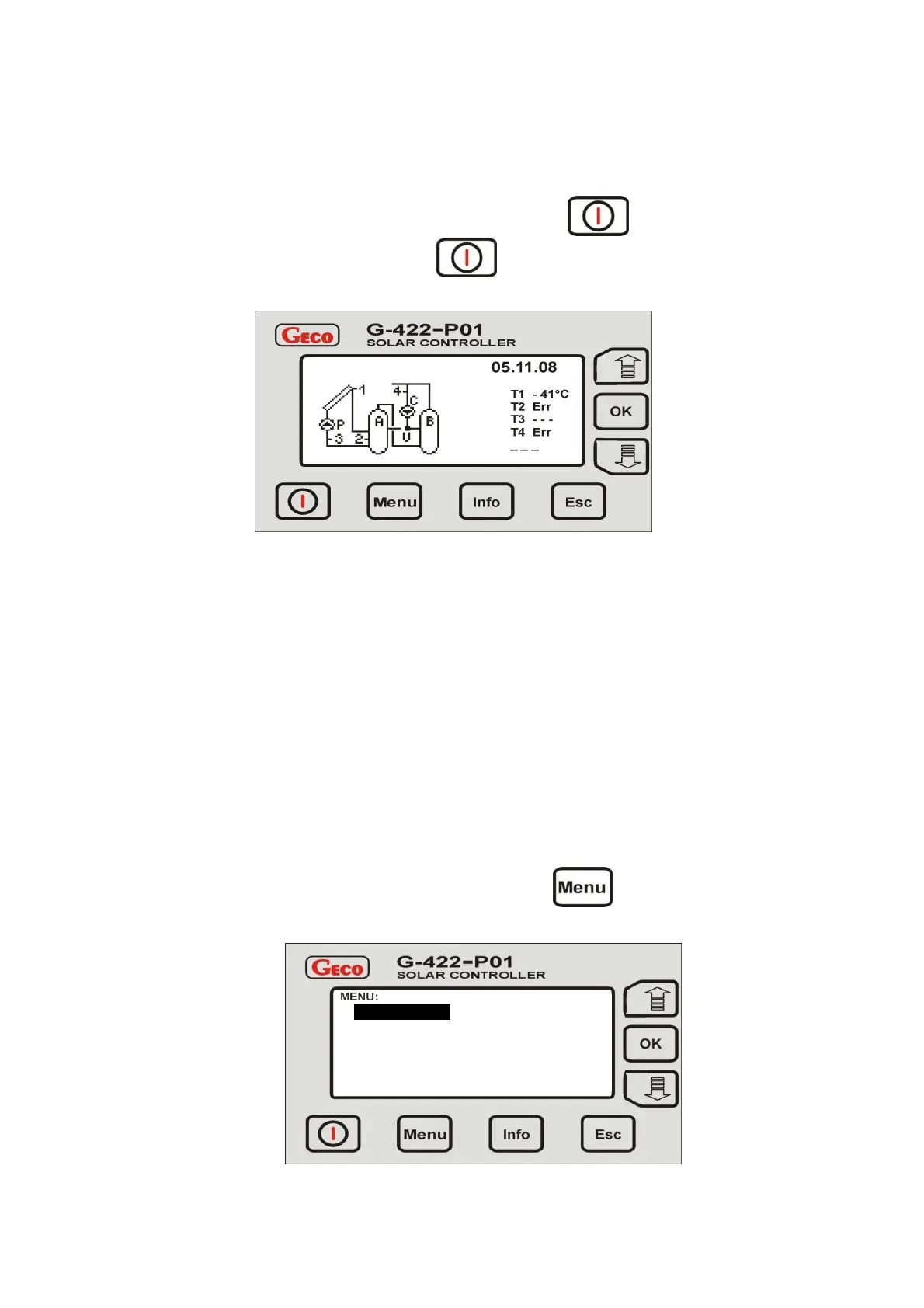
In order to select the desired collector installation configuration, select the main menu by pressing . The LCD screen will display the main menu
list, as shown below in picture 3:
Pic. 3. Screen display of the main menu.
Parameters
Date and Time
Manual Control
Language
 Loading...