10
Fig. 15. Schematic and electrical diagram of installation no 13.
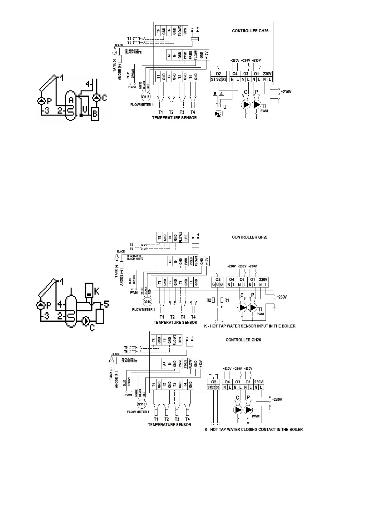
4.14 System for heating a combi heater with solar collector, an electrical boiler or liquid-fuel boiler and a solid-fuel boiler - scheme no 14
Controlling the P collector pump
Similarly as in scheme no 1 - description in point 4.1.
Controlling the K boiler
Similarly as in scheme no 3 - description in point 4.3.
Controlling the C solid-fuel boiler pump
Similarly as in scheme no 6 (in scheme 6 the pump is denoted as K) - description in point 4.6.
Moreover, C pump operation results in switching the K boiler off if the option K boiler blockade when C boiler switch on is on in control parameters. If the blockade is off, the K
boiler can work simultaneously with the solid-fuel boiler.
ATTENTION ! Different parameters have been used in the diagram (“Max. temp. T4 OFF heat source” – for heating with the use of an electrical boiler or a liquid fuel boiler
and “Max. water temperature from boiler C” – for heating with the use of a fireplace or a solid-fuel boiler) for heating water in the upper part of the combi heater
measured by the T4 sensor.
Fig. 16. Schematic and electrical diagram of installation no 14.
4.15 Tap water heating system - controlling operation of solar collector pumps located in various directions - scheme no 15
Controlling the P collector pump
Similarly as in scheme no 1 - description in point 4.1.
Controlling the K collector pump
The K collector pump will be switched on if the solar collector reaches a temperature of T3 which is hotter by the “Temp. T1&T2 difference – pump ON” value than the T2
temperature in the lower part of the heater. The pump will remain switched on until the difference in temperatures (T1-T3) falls below the set value and the temperature in the heater
 Loading...