Do you have a question about the Hexagon TP-R-400 and is the answer not in the manual?
Overview of the touch probe, including preface, safety, and validity.
Details the intended use and applications of the TP-R-400 touch probe.
Lists regulatory compliance and certifications for different regions.
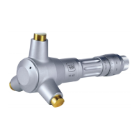
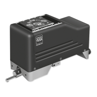
Identifies and illustrates the main parts of the TP-R-400 system.
Presents different configurations of the TP-R-400 with various measuring units.
Provides detailed technical data including general specs and unit-specific data.
Displays physical dimensions for different measuring unit configurations.
Illustrates the radio transmission and reception area of the probe.
Lists what is included, available accessories, and spare parts.
Lists required tools and equipment for operation and setup.
Covers initial setup and commissioning procedures for the touch probe.
Step-by-step guide for installing and replacing the stylus.
Instructions for attaching and removing tool holders for the probe.
Procedure for replacing the battery in the touch probe.
Guides on configuring settings and pairing the probe with a receiver.
Procedure for accurately aligning the stylus with the spindle center.
Instructions for adjusting the probe using a 90° adapter.
Explains the meaning of the LED ring indicators and their patterns.
| Brand | Hexagon |
|---|---|
| Model | TP-R-400 |
| Category | Measuring Instruments |
| Language | English |