Do you have a question about the HEXING HXCG3A-P and is the answer not in the manual?
Provides a high-level overview of the Hexing G3 smart metering system and its capabilities.
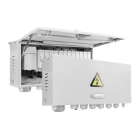
Details the material, robustness, and design aspects of the G3 smart metering system cabinet.
Illustrates the internal layout of the G3 meter cabinet, showing device placement and connection points.
Describes the main components of the G3 system, including HXCG3A Cabinet, HXP200 meter, HXEC201 DC, EV500 CIU, and EV800 CIU.
Describes the physical construction of the main circuit breaker available in G3 meter cabinets.
Explains the markings and information present on the main circuit breaker's nameplate.
Details the electrical and mechanical specifications for the main circuit breakers used in the G3 system.
Provides instructions on the factory pre-installation of the main circuit breaker and its cables.
Details the LCD display of the CIU EV500, including segments, features, and operating parameters.
Illustrates and describes individual display segments used on the CIU EV500 for conveying information.
Explains the different display modes for the CIU EV500, including automatic scroll and keypad input.
Describes the backlight functionality for the CIU EV500 keypad and LCD screen.
Lists short codes used with the CIU EV500 for accessing various data and functions.
Details the physical features and LCD display of the CIU EV800.
Explains the display modes for the CIU EV800, focusing on automatic scroll and its configurable contents.
Describes the status indicators on the CIU EV800 LCD, showing tamper and event status.
Explains the functionality and keypad layout of the IR remote controller for the CIU EV800.
Lists short codes used with the CIU EV800 via IR remote for accessing data and functions.
Lists management tokens for setting power, clearing balance, changing keys, and switching payment modes.
Provides a list of test tokens for various meter functions like full test, relay test, and LCD display.
Describes the wiring methods for single-phase two-wire, single-phase three-wire, and two-phase three-wire meters.
Details how energy is measured, registered, and the range of measurement.
Lists the parameters available for instantaneous measurement, such as voltage, current, and power factor.
Explains the content and capacity for daily and monthly frozen data stored by the meter.
Describes how the meter communicates with the master station via 3G/4G or Wi-SUN for data and control.
Explains local communication using HHU for meter reading, parameter setting, and maintenance.
Details the terminals in the power module for door open, meter reading, and maintenance functions.
Explains the meaning of the LEDs on the HXP200 meter, indicating energy consumption, relay status, and payment mode.
Describes the LED indicators for the Data Collector, covering Run, RS485, GPS, and communication modules (3G/4G, Wi-SUN).
Details the LED indicators for the CIU, including credit status and alarm/consumption indication.
Explains how the collector detects and reports cabinet door opening events.
Describes how over-temperature data is collected and reported as an alarm event.
Provides dimensional drawings for various devices in the G3 system, starting with the 12-spot standard cabinet.
Details the dimensions for the 12-spot cabinet variant that includes a main circuit breaker.
Presents the dimensional information for the 18-spot cabinet configuration.
Shows the dimensions of the Data Collector unit.
Provides dimensions for the communication module used within the data collector.
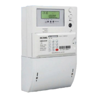
Details the dimensions for the meters, starting with the 1-phase 2-wire type.
Presents the dimensional drawings for the CIU EV500.
Shows the dimensional information for the CIU EV800.
Lists and illustrates the necessary accessories for installing the G3 meter cabinet, such as hoop brackets and cross arms.
Provides essential precautions and procedures before commencing the installation of the meter cabinet.
Details the method for installing the meter cabinet on poles that lack pre-drilled holes, using a special hoop bracket.
Guides the user through the process of installing the meter cabinet on a wall, including tools and steps.
Lists the tools required for wiring the meter cabinet, such as cross screwdrivers and hexagon wrenches.
Provides wiring diagrams for 1p3w and 1p2w meter configurations within the G3 system.
| Product Type | Smart Meter |
|---|---|
| Current | 5(100)A |
| Model | HXCG3A-P |
| Manufacturer | Hexing |
| Display | LCD |
| Protection | IP54 |
| Category | Measuring Instruments |
| Phase | Three-phase |
| Communication | Infrared, RS485 |
| Voltage | 3x 220/380V |
| Standard | IEC 62052-11 |
| Type | Electronic Energy Meter |
| Frequency | 50Hz/60Hz |