А
АбдуллаOct 23, 2025
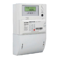
Здравствуйте!HEXING HXE 110 Может обнаружить автоматический хищение разнм способом
Здравствуйте!HEXING HXE 110 Может обнаружить автоматический хищение разнм способом
Specifies the scope of the user manual, applying only to Hexing meter types mentioned in the title.
Outlines the manual's purpose: providing technical information for meter use, maintenance, and functions.
Identifies target audience for the manual, including design, testing, operation, and maintenance personnel.
Details the meter's power source and the function of the backup battery for RTC and event detection.
Describes optical, RS485, and pluggable modules for data communication and AMI system integration.
Covers import, export, combined, and net active energy accumulation modes and tariffs.
Details import, export, and quadrant-specific reactive energy accumulation modes and tariffs.
Lists support for import and export apparent energy accumulation, total and per tariff.
Enables real-time monitoring of voltage, current, power, frequency, and phase angles.
Describes the full-segment LCD layout, data display, OBIS display, and voltage indicators.
Explains the meaning of various symbols and indicators shown on the LCD screen.
Explains auto-scrolling, manual, and power-off display modes for user interaction.
Details how the LCD backlight is activated on demand via button press.
Explains slide and block interval methods for calculating Maximum Demand over specified periods.
Lists various registers storing active, reactive, and apparent demand with time stamps and tariffs.
Describes methods for resetting Maximum Demand values: auto, manual button, and command.
Details capacity, default applications, and max capture items for different load profile configurations.
Lists the data objects that can be captured and stored within load profiles, with their byte sizes.
Explains the daily data freezing process, including retention period and freezing time.
Covers capacity, automatic/manual billing, and data objects supported for monthly billing.
Defines status codes (Disconnected, Connected, Ready) and their descriptions for relay control.
Defines transform numbers and names for remote, manual, and local relay control operations.
Details disconnection/reconnection modes for various control types.
Details the priority order for various relay operation events like overload and credit status.
Details event codes and judgments for standard events like clock adjustments and billing.
Lists event codes and judgments for tampering events such as cover opening and magnetic disturbance.
Records events related to relay control actions such as manual or remote disconnection.
Records events related to power grid disturbances like under/over voltage and over current.
Logs events related to communication module status, signal quality, and registration failures.
Describes the internal and optional external battery, low battery detection, and working lifetime.
Explains Daylight Saving Time functionality, configuration, and restrictive conditions for its application.
Details TOU tariff support, holiday types, season tables, and weekly/daily timetable configurations.
Guides users on entering tokens for successful recharging, handling errors, and understanding credit transfer.
Covers managing meter settings like maximum power, clearing credit, and changing meter keys.
Provides specific tokens for performing full tests, relay tests, LCD tests, and displaying meter data.
Explains the process for cancelling meter registration and obtaining refund tokens.
Lists short codes available for consumers to quickly retrieve specific meter information.
Describes the active LED's function indicating energy consumption and status.
Explains the alarm LED's behavior, lighting up for tamper events and turning off when cleared.
Describes the reactive LED's function indicating reactive energy consumption and status.
Explains the credit LED's indication of balance status and power presence in prepayment mode.
Details the optical port's compliance with standards, physical interface, and communication protocols.
Specifies communication protocol, baud rate, and data bit settings for the RS485 interface.
Details baud rate, compliance, and functionality for PLC communication modules.
Details baud rate, compliance, and functionality for Wisun communication modules.
Outlines communication standards and online modes for 4G modules, supporting client and server functions.
Illustrates wiring diagrams for 1P2W and 1P3W connections, including terminal block layouts.
Provides overall dimensions of the smart meter and detailed installation dimension drawings.
Lists essential tools for meter installation, including screwdrivers, drill, and wire stripper.
Covers safety precautions, environmental requirements, and pre-installation checks for meter installation.
Step-by-step guide for mounting the meter, connecting wires, and ensuring secure installation.
Details checks to perform after installation, including breaker status, meter display, and relay position.
Provides instructions for safely powering off, removing the meter, and handling disconnected cables.
Guides users on troubleshooting common issues like LCD display or data communication failures.
Outlines the procedure for handling meter repairs, including un-installation, fault description, and shipping.
Advises on using dry cloths for cleaning the meter surface, warning against water usage.
Describes steps for checking meter errors and functions using a test bench and communication.
Lists electrical specifications such as reference voltage, current ratings, starting current, and frequency.
Details accuracy classes for active and reactive energy measurement, and compliance with standards.
Provides mechanical specifications including connection type, weight, dimensions, and terminal details.
| Brand | HEXING |
|---|---|
| Model | HXE110 |
| Category | Measuring Instruments |
| Language | English |