User manual for single-phase meter
4
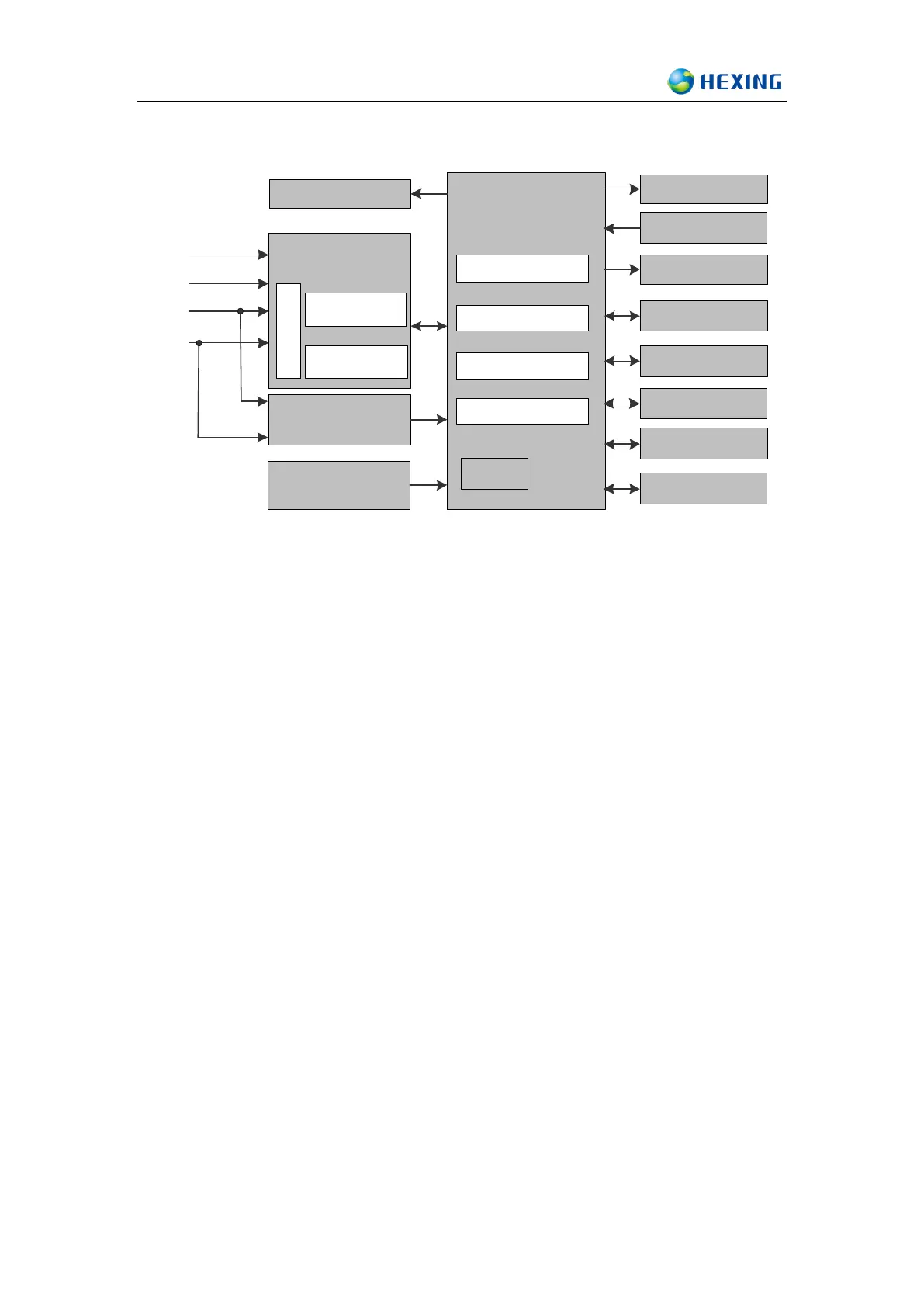
4 Working Principle
Micro Controler
Measuring
System
A
D
Calibration
Power Supply
Backup power Supply
LED Diode
Data process
Time of use
Load profile
Event record
RTC
Signal
processing
Non-volatile
Memory
EEPROM Memory
Optical Interface
LCD Display
Relay
RS-485 Interface
L1
N
I2
I1
Button
Input&Output
Inputs:
The main inputs to the meter are:
Phase line L, neutral line N, current I1(main loop),neutral line I2(secondary loop)
For the power supply to the meter
For providing sampling signals
Buttons
Switch displaying items
Control relays manually
Communication interface of external data signal input
Signal input
Output:
The meter has the following outputs:
LCD liquid crystal display
Pulse of meter testing
Output signals from the communication interface
Measuring system:
Sample and calculate the input power grid signal to get related power grid information,
including following parameters:
Active power
Reactive power
Voltage
Current
Frequency
Power factor
Electric test pulse:
Active or Reactive power pulse is generated for accuracy test.
Power supply: