Elfin-EG41 用户手册
http://www.iotworkshop.com - 9 -
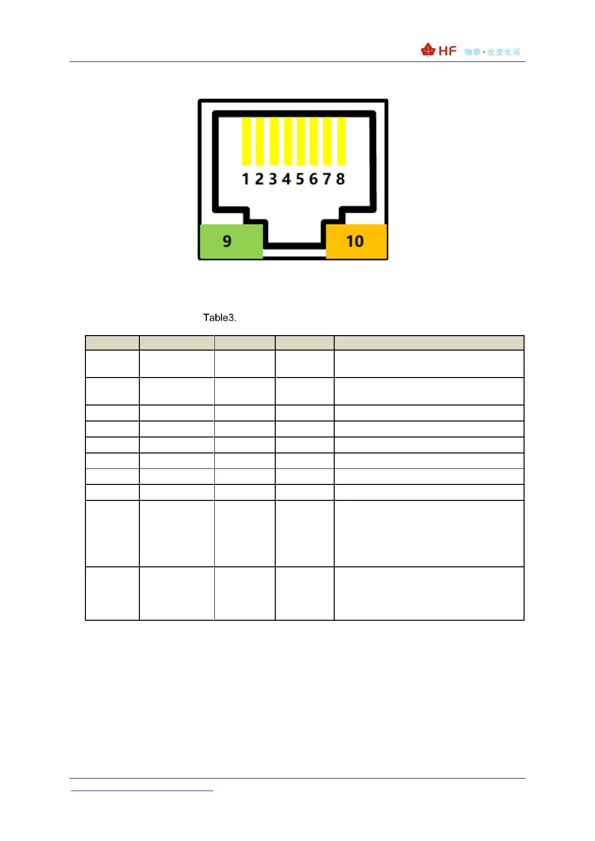
2.2. Elfin-EG41 Pin Definition
Figure 2. Elfin-EG41 RJ45 Interface Pin
Elfin-EG41 Interface Definition
Boot On: Power is OK.
2s Off -> 2s On: cellular network Register
is OK.
0.1s Off -> 0.1s On: cellular network data
is transferring.
Off: No data transfer
0.3s Off -> 0.9s On: UART TX Output
0.3s Off -> 0.3s On: UART RX Receive
On: UART bidirection.
<Notes>:
I — Input; O — Output; Power—Power Supply
Note
PIN1/2 is TTL UART, PIN5/6 is RS485 interface, it is same UART for internal MCU, just the
hardware driver is different. Choose either TTL or RS485