User Manual
The module reserves 5 pin holes, with a total of five signal PINs VCC, GND, OUT, P2 and P3.
The PIN distance is 2.54mm. If you need to tune the distance and delay time and other parameters,
you can hang or pull down P2 and P3.
The state matches the specific resistance on the module to select the corresponding gear or use the
external MCU reserved on the module to rewrite the internal parameters. The following table shows
the definition of each PIN:
LDO is not attached by default. Lithium battery or dry battery
can be used for direct power supply (2.7~4.8V). If the power
supply voltage exceeds 5V, LDO needs to be added. At this
time, the power supply VCC is 5~12V
Output signal is high and low level(0V/2.2V)
Receiving gain gear selection
Delay time gear selection
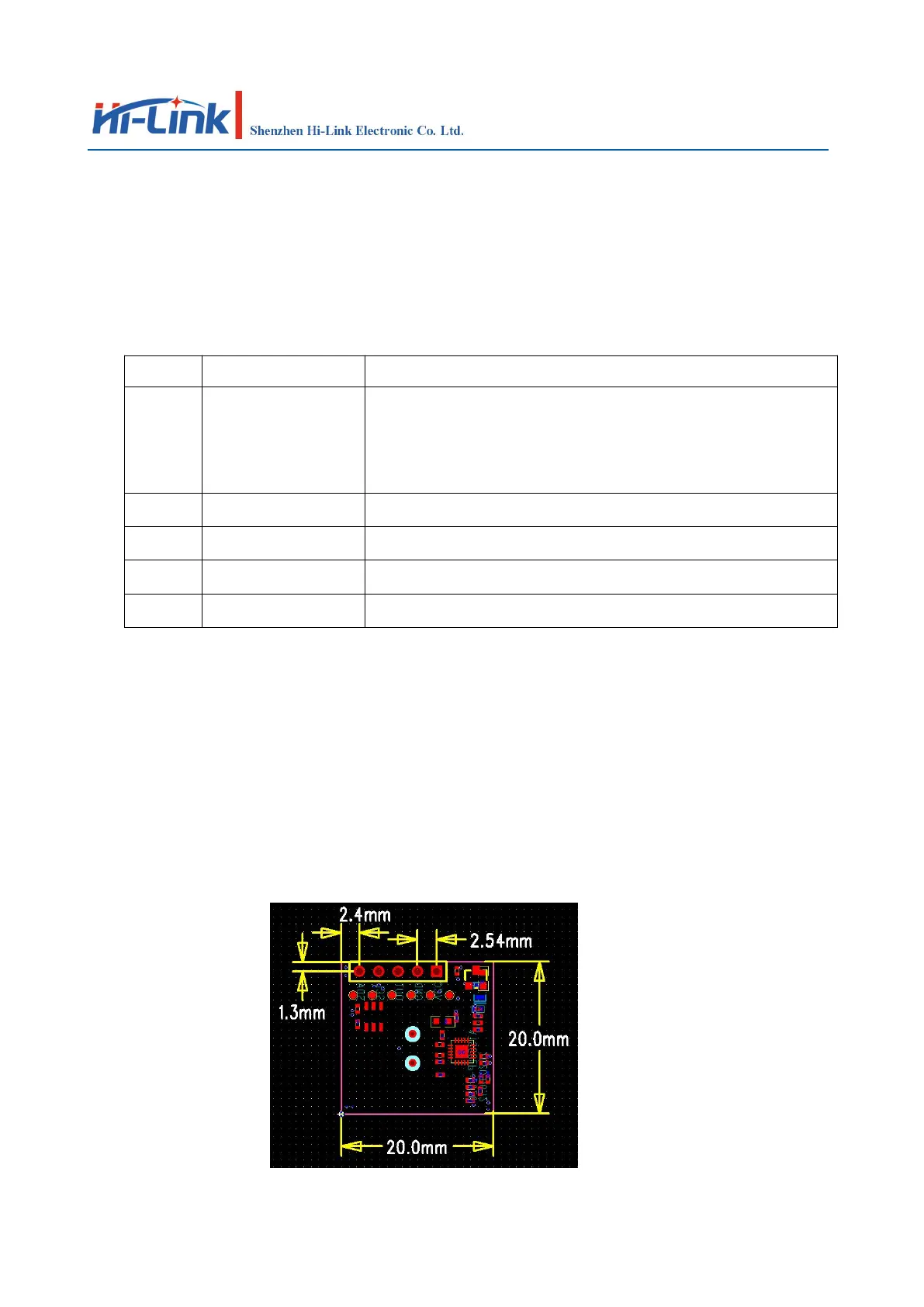
3. Module size and pin position
The figure below is a schematic diagram of the size and pin position of the module.
The length and width of the module are 20mm*20mm, and the factory default does not have pins
The overall thickness is 2.5mm, if you need to bring pins, the default pin height is 12mm.
 Loading...