User Manual
4. Electrical parameters
LDO is not attached by default
Adjustable according to specific
needs
Adjustable according to specific
needs
5. Sensing time and sensing distance adjustment
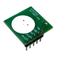
The P2 and P3 pins on the HLK-LD012-5G module are used to select different sensing distances
and delay gears; P2 is used to adjust the sensing distance, which can be provided with the 3
resistors (th0, th1, th2) reserved on the module 16 different sensing distance options.
When P2 is suspended or pulled up, the sensing distance of the module is far; when P2 is pulled
down, the receiving gain is reduced by 18dB and the sensing distance is short. The three distance
adjustment resistors on the module are used to adjust the threshold of the inductive judgment. The
resistance bit NC represents 1, and the 0 ohm resistor represents 0. Refer to Figure 4 for the status
of the 3 resistance bits and the corresponding threshold. The smaller the threshold, the farther the
sensing distance.
P3 is used to select the pull-up time of the OUT signal after sensing. When P3 is floating or pulled
 Loading...