1 PREPARATION
Remove
the
screw
from
the
bottom
of
the
case. Remove all
of
the
screws around
the
outside
of
the
panel
that
hold
the
tester
to
the
case.
Remove
the
tester
from
the
case
a nd set
it
up
on spacers
so
that
the
front
panel
is
facing up in
the
normal operating position. Before applying
power
adjust
the
mechanical zero
on
the
meters
that
have
that
capability
to
set
the
pointers exactly
at
the zero line on
the
scale.
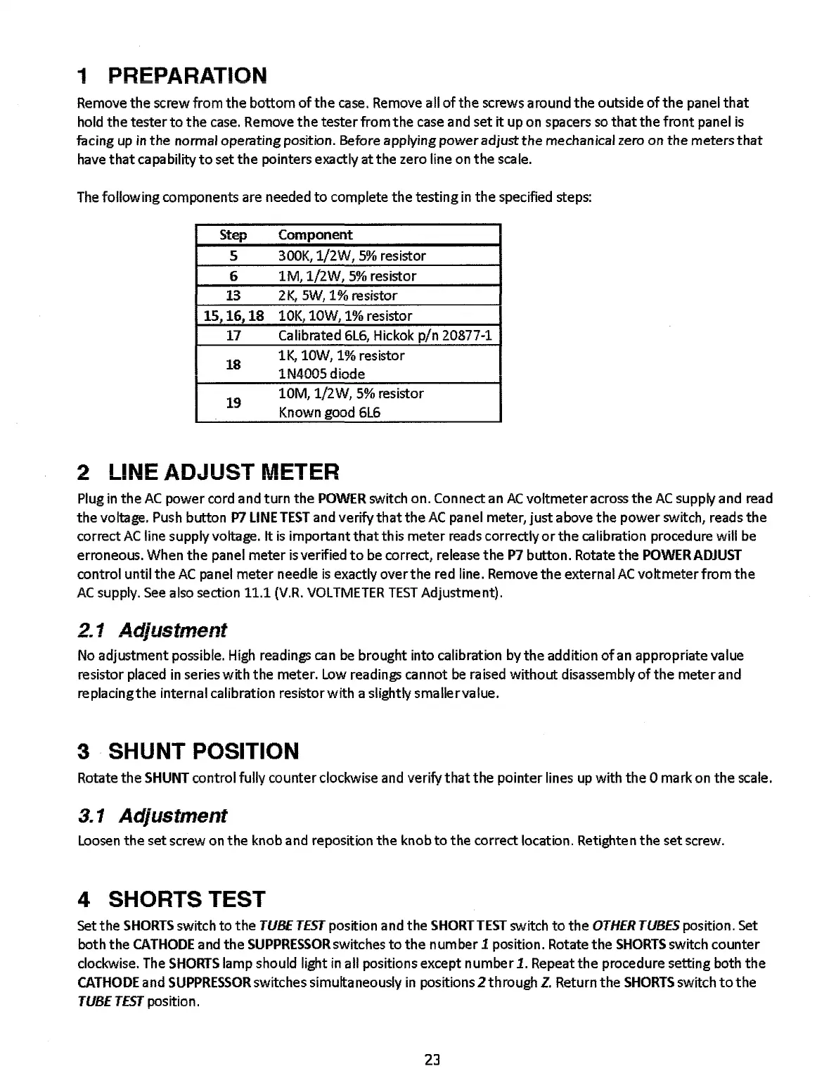
The
following
components are needed
to
complete
the
testing
in
the
specified steps:
Step
Component
5 300K, 1/2W,
5%
resistor
6
1M,
1/2W,
5%
resistor
13
2K,
5W, 1% resistor
15,16,18
10K,
lOW,
1% resistor
17 Calibrated
6L6,
Hickok
pin
20877-1
18
lK,
lOW, 1% resistor
lN4005
diode
19
10M,
1/2W,
5%
resistor
Known good 6L6
2 LINE ADJUST METER
Plug
in
the
AC
power
cord and
turn
the
POWER
switch on. Connect an
AC
voltmeter
across
the
AC
supply and read
the voltage.
Push button
P7
LINE
TEST
and verify
that
the
AC
panel meter,
just
above
the
power
switch, reads
the
correct
AC
line supply voltage. It
is
importa
nt
thatth
is
meter
reads correctly
or
the
calibration proced ure
will
be
erroneous. When
the
panel
meter
is
verified
to
be correct, release
the
P7
button. Rotate
the
POWERADJUST
control until
the
AC
panel
meter
needle
is
exactly
overthe
red line. Remove
the
external
AC
voltmeter
from
the
AC
supply.
See
also section 11.1
(V.R.
VOLTMETER
TEST
Adjustment).
2.1
Adjustment
No adjustment possible. High readings can
be
brought into calibration by
the
addition
of
an
appropriate value
resistor placed
in
series
with
the
meter. Low readings
ca
n
not
be
ra
ised
without
disassembly
of
the
mete
rand
replacing
the
internal calibration resistor
with
a slightly smallervalue.
3 SHUNT POSITION
Rotate
the
SHUNT control fully counter clockwise and verify
that
the
pointer
lines up
with
the
0
ma
rk on
the
scale.
3.1
Adjustment
Loosen
the
set screw on
the
knob and reposition
the
knob
to
the
correct location. Retighten
the
set screw.
4 SHORTS TEST
Set
the
SHORTS
switch
to
the
TUBE
TESf position and
the
SHORT
TEST
switch
to
the
OTHER
TUBES
position. Set
both
the
CATHODE
and
the
SUPPRESSOR
switches
to
the
number
1 position. Rotate
the
SHORTS
switch
counter
clockwise. The
SHORTS
lamp should light in all positions except
number
1. Repeat
the
procedure setting both
the
CATHODE
and
SUPPRESSOR
switches simultaneously in positions 2 through
z.
Return
the
SHORTS
switch
to
the
TUBETESf position.
23