14.1 Adjustment
If balance
is
not
obtainable replace
the
83
and/or
SY3
tube.
15
!\'~ETER
BRIDGE BALANCE
Set
the
FUNCTION
switch
to
the
C (15,000) position.
Con
nect a 10K,
lOW,
1% resistor betwee n pins 3 and 8
of
the
octa I socket.
Press
P4
(locked) and obse rve
that
the
meter
reads zero. Adj ust
R8
to
trim
out
sma
II
errors. Release
P4
and remove
the
resistor.
15.1 Adjustment
If bala nce
is
not
correct check
the
bridge resistors
R37/
500 ohms,
R38
/ 60 ohms,
R39
/ 40 ohms,
R40/
40 ohms,
R41/60
ohrns and
R42/500
ohms
for
proper value. Note
that
resistors
of
equal value
in
this series should
be
matched closely
in
value
for
good bridge balance. Also confirm
that
the
plate power supply
is
correctly balanced
as
tested
in
step
14
(POWER
SUPPLY
BALANCE
CALIBRATION).
16
~
..
~UTUAL
CONDUCTANCE READING TEST
Verify
that
the
panel switches are set up
to
the
conditions
as
given in
the
list
immediately
following
step 6.
(HS
5348-1) FILAMENT
at
6.3 volts.
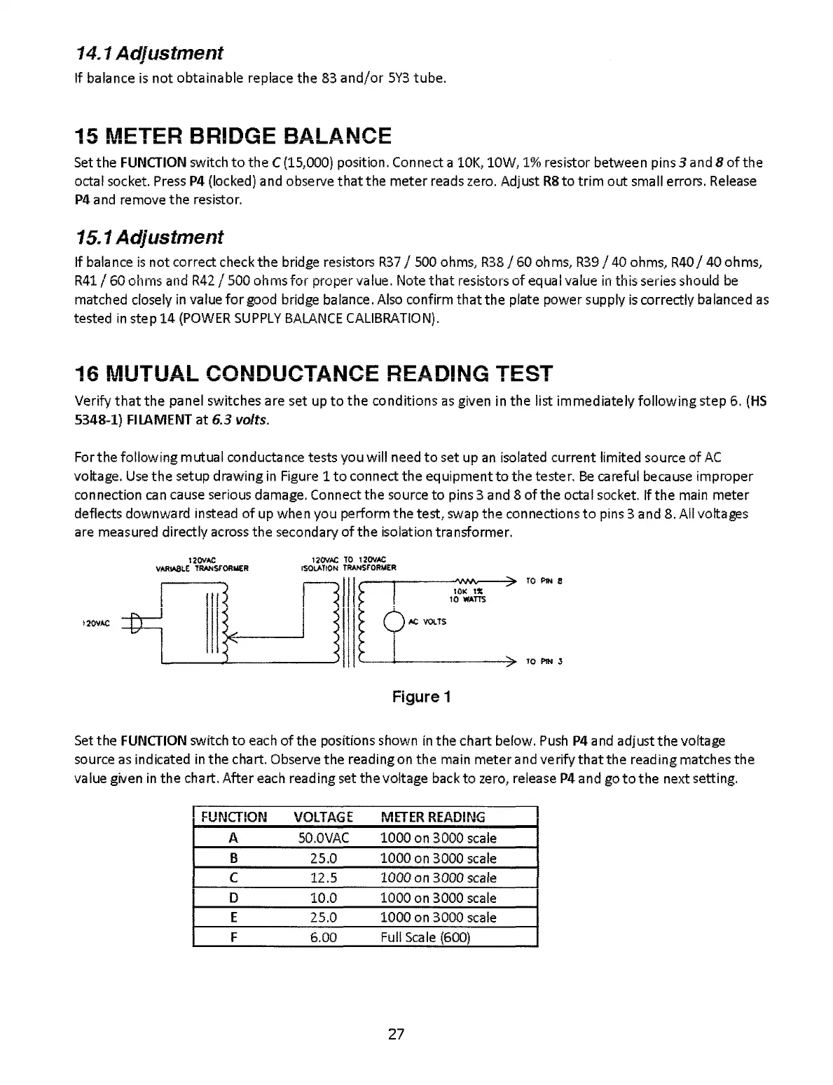
Forthe
following
mutual
conductance tests you
will
need
to
set up
an
isolated current limited source
of
AC
voltage.
Use
the
setup drawing
in
Figure 1
to
connect
the
equipment
to
the
tester.
Be
careful because
improper
connection
can
cause serious damage. Connect
the
source
to
pins 3 and 8
of
the
octal socket. If
the
main
meter
deflects
downward
instead
of
up when you perform
the
test, swap
the
connections
to
pins 3 and 8. All voltages
are measured directly across
the
secondary
of
the
isolation
tra
nsformer.
t20VAC
12011.t.C
vAAlASLE
TRANSfORIER
120VAC
TO
12011AC
ISOlATION
TRANSFOR!.IER
Figure 1
TO
PIN
8
>
TO
PIN
l
Set
the
FUNCTION
switch
to
each
of
the
positions shown
in
the
chart befow.
Push
P4
and adjust
the
voftage
source
as
indicated
in
the
chart. Observe
the
reading on
the
main
meter
and
verify
that
the
reading matches
the
value given
in
the
chart.
After
each reading set
the
voltage back
to
zero, release
P4
and go
to
the
next setting.
.
"'"'11"'-'1111
V,,",L.
•
..
IVI
...
I
Ln.
',\;"',",,-&.11
,....:;
A
sO.OVAC
1000
on 3000 scale
B
25.0
1000
on 3000 scale
C
12.5
1000 on 3000 scale
0 10.0
1000
on 3000 scale
E
25.0
1000
on 3000 scale
F
6.00
Full
Sca
Ie
(600)
27