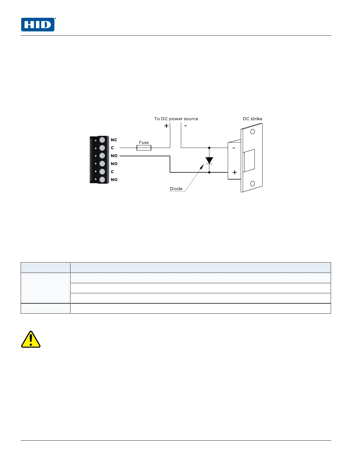
2.6 Control output wiring
Six Form-C contact relays are provided for controlling door strikes or other devices. Load switching can
cause abnormal contact wear and premature contact failure. Switching of inductive loads (strike) also causes
EMI (electromagnetic interference) which may interfere with normal operation of other equipment. To
minimize premature contact failure and to increase system reliability a contact protection circuit must be
used. The following two circuits are recommended. Locate the protection circuit as close to the load as
possible (within 12 inches [30 cm]), as the effectiveness of the circuit will decrease if it is located further
away.
Use sufficiently large gauge of wires for the load current to avoid voltage loss.
Diode selection
n Diode current rating > 1x strike current.
n Diode break down voltage: 4x strike voltage.
n For 12 V DC or 24 V DC strike, diode 1N4002 (100V /1A) typical.
2.7 Jumpers
Jumper Description
J1 Reader power select
12V = 12 V DC at reader ports. See caution below.
PT = VIN “Passed Through" to reader ports
J4 RS-485 termination, install in first and last units only
Note: All other jumpers are for factory use only.
Caution: The input power (VIN) must be 20 V DC minimum if the 12 V DC selection is to be used.
PLT-05248, A.2 10 June 2021
Powering
Trusted Identities
HIDMercury™ MR52-S3 Reader Interface
Installation and Specifications
 Loading...