Revision D assembly:
The Interface is for use in low voltage, class 2 circuits only.
The installation of this device must comply with all local fire and electrical codes.
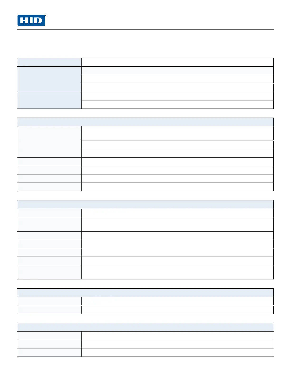
Primary power 12 to 24 V DC ± 10%, 550 mA maximum (reader current not included)
Outputs Six Form-C relays
Normally open contact (NO) contact: 5 A @ 30 V DC resistive
Normally closed contact (NC) contact: 3 A @ 30 V DC resistive
Inputs Eight unsupervised/supervised, standard EOL: 1k/1kΩ , 1%, ¼ watt
Two unsupervised, dedicated for cabinet tamper and UPS fault monitoring
Reader interface
Power
(jumper selectable)
12 V DC ± 10% regulated, 300 mA maximum each reader
(input voltage (VIN) must be greater than 20 V DC)
or
12 to 24 V DC ± 10% (input voltage passed through), 300 mA maximum each reader
Data inputs TTL compatible, F/2F or 2-wire RS-485
LED output TTL compatible, high > 3 V, low < 0.5 V, 5 mA source/sink maximum
Buzzer output Open collector, 12 V DC open circuit maximum, 40 mA sink maximum
Communication 2-wire RS-485: 9600, 19200, 38400 or 115200 bps
Cable requirements
Power 1 twisted pair, 18 AWG
RS-485 I/O devices 1 twisted pair with drain wire and shield, 24 AWG, 120Ω impedance, 4,000 feet
(1,200 m) maximum
Alarm inputs One twisted pair per input, 30Ω maximum
Outputs As required for the load
Reader data (TTL) 6-conductor, 18 AWG, 500 feet (150 m) maximum
Reader data (F/2F) 4-conductor, 18 AWG, 500 feet (150 m) maximum
Reader data (RS-485) 1 twisted pair with drain wire and shield, 24 AWG, 120Ω impedance, 2,000 feet
(610 m) maximum
Mechanical
Dimension 6 inches (15 2 mm) W x 8 inches (203 mm) L x 1 inches (25 mm) H
Weight 11 oz. (312 g) nominal
Environment
Storage temperature -55 to +85°C
Operating temperature 0 to +70°C
Humidity 5 to 95% RHNC
PLT-05248, A.2 15 June 2021
Powering
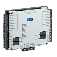
Trusted Identities
HIDMercury™ MR52-S3 Reader Interface
Installation and Specifications
 Loading...