13.56 MHZ/2.4 GHz Contactless
SRD Model: 25B
HID
®
Signo
™
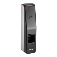
25B
Biometric Reader/Controller
Install Guide
Supplied parts
• HID Signo Biometric Reader/Controller 25B (1)
• Installation Guide (1)
• Screw (1) – for attaching the reader to the backplate
Recommended parts (not supplied)
• Cable, 5-9 conductor (Wiegand), 4 conductor Twisted Pair Over-All Shield and UL approved, Belden
3107A or equivalent (OSDP)
• Certified LPS DC power supply
• Security tool HID 04-0001-03 (for anti-tamper screw)
www.hidglobal.com/PLT-04027
• Scan the QR code or visit the link to see the multi-language electronic version of this
document.
• Lisez le code QR ou suivez le lien pour consulter la version française de ce document.
• Escanee el código QR o visite el vínculo para consultar la versión en Español de este
documento.
• Scannen Sie den QR-Code oder öffnen Sie den Link für die deutsche Version dieses
Dokuments.
• Faça a leitura do código QR ou acesse o link da versão em português deste documento.
• Scansiona il codice QR o visita il link della versione Italiana di questo documento.
• Отсканируйте QR-код или пройдите по ссылке, чтобы получить версию этого
документа на русском языке.
• 扫描 QR 码或访问此 文档的中文版本的链接。
•この文書の日本語版を表示するには、QRコードをスキャンするか、リンクをクリックします。
•QR코드를 스캔하거나 링크를 방문하면 이 문서의 한국어 버전을 볼 수 있습니다.
ATTENTION
Observe precautions for handling ELECTROSTATIC SENSITIVE DEVICES
1. Mount the mounting plate
2 Wire the 25B
Light bar
Biometric reader
(requires set up in HID Biometric Manager)
Turn on the power.
The reader should beep and the light bar should flash.
Test the reader with a card.
The reader should beep and the light bar should flash.
3. Secure the 25B to the mounting plate
4. Power and test the reader
5. Download and install HID Biometric Manager
1. Insert the reader into the backplate.
2. Latch the reader.
3. Secure the reader to the backplate using the
supplied screw.
Screws not supplied.
Function Group Wire Color Function AWG Max Length
1
RS-485
Green RS-485 A
24
4,000 ft
(1,219 m)
Tan RS-485 B
Black RS-485 Ground
Relay
Gray Relay – Common
22
500 ft
(152 m)
Yellow Relay – Normally Open
Orange Relay – Normally Closed
Inputs
(Controller
mode only)
Pink REX Input (Supervised)
Gray DPS Input (Supervised)
Black Input Ground
Wiegand Port
Green D0
White D1
Brown RED
Orange Greeb
Yellow BUZ
Blue HOLD
Violet TPR
Black Ground
DC Power Red Power +12V
Black Power Ground
Function Group Connector Function Max Length
Network
RJ45
socket
Ethernet
328 ft (100 m)
(CAT5/CAT5E/CAT6)
Pigtail wires
18” (0.46m)
Ethernet cable
18” (0.46m)
1
RS-485 = Max bus length 4,000 ft - 24 AWG (1,219 m)
Max length between nodes: 1,640 ft - 24 AWG (500m)
Note: Bond the ground wires of the Signo 25B power supply and the panel power supply.
IMPORTANT: The 19 pigtail wires should be cut to size for wall mounted application.
IMPORTANT: DO NOT cut the Ethernet cable.
Note: Wiring the reader incorrectly may permanently damage the reader.
Note: For readers with Tamper Evident Labels, inspect your reader after first unboxing. If any
seals are broken, please contact HID Technical Support.
Tamper evident labels (location may vary according to the reader model)
1
1
2
3
Visit https://www.hidglobal.com/signo25b and download the HID
Biometric Manager Installer. Once the .exe file has downloaded,
double-click the file to install HID Biometric Manager, following the
on-screen prompts.
For further details, refer to the HID Signo Biometric Reader/
Controller 25B Administration Guide (PLT-04029), which is
available for download from https://www.hidglobal.com/signo25b
13.56 MHZ/2.4 GHz Contactless
SRD Model: 25B
HID
®
Signo
™
25B
Biometric Reader/Controller
Install Guide
Supplied parts
• HID Signo Biometric Reader/Controller 25B (1)
• Installation Guide (1)
• Screw (1) – for attaching the reader to the backplate
Recommended parts (not supplied)
• Cable, 5-9 conductor (Wiegand), 4 conductor Twisted Pair Over-All Shield and UL approved, Belden
3107A or equivalent (OSDP)
• Certified LPS DC power supply
• Security tool HID 04-0001-03 (for anti-tamper screw)
www.hidglobal.com/PLT-04027
• Scan the QR code or visit the link to see the multi-language electronic version of this
document.
• Lisez le code QR ou suivez le lien pour consulter la version française de ce document.
• Escanee el código QR o visite el vínculo para consultar la versión en Español de este
documento.
• Scannen Sie den QR-Code oder öffnen Sie den Link für die deutsche Version dieses
Dokuments.
• Faça a leitura do código QR ou acesse o link da versão em português deste documento.
• Scansiona il codice QR o visita il link della versione Italiana di questo documento.
• Отсканируйте QR-код или пройдите по ссылке, чтобы получить версию этого
документа на русском языке.
• 扫描 QR 码或访问此 文档的中文版本的链接。
•この文書の日本語版を表示するには、QRコードをスキャンするか、リンクをクリックします。
•QR코드를 스캔하거나 링크를 방문하면 이 문서의 한국어 버전을 볼 수 있습니다.
ATTENTION
Observe precautions for handling ELECTROSTATIC SENSITIVE DEVICES
1. Mount the mounting plate
2. Wire the 25B
Light bar
Biometric reader
(requires set up in HID Biometric Manager)
Turn on the power.
The reader should beep and the light bar should flash.
Test the reader with a card.
The reader should beep and the light bar should flash.
3. Secure the 25B to the mounting plate
4. Power and test the reader
5. Download and install HID Biometric Manager
1. Insert the reader into the backplate.
2. Latch the reader.
3. Secure the reader to the backplate using the
supplied screw.
Screws not supplied.
Function Group Wire Color Function AWG Max Length
1
RS-485
Green RS-485 A
24
4,000 ft
(1,219 m)
Tan RS-485 B
Black RS-485 Ground
Relay
Gray Relay – Common
22
500 ft
(152 m)
Yellow Relay – Normally Open
Orange Relay – Normally Closed
Inputs
(Controller
mode only)
Pink REX Input (Supervised)
Gray DPS Input (Supervised)
Black Input Ground
Wiegand Port
Green D0
White D1
Brown RED
Orange Greeb
Yellow BUZ
Blue HOLD
Violet TPR
Black Ground
DC Power Red Power +12V
Black Power Ground
Function Group Connector Function Max Length
Network
RJ45
socket
Ethernet
328 ft (100 m)
(CAT5/CAT5E/CAT6)
Pigtail wires
18” (0.46m)
Ethernet cable
18” (0.46m)
1
RS-485 = Max bus length 4,000 ft - 24 AWG (1,219 m)
Max length between nodes: 1,640 ft - 24 AWG (500m)
Note: Bond the ground wires of the Signo 25B power supply and the panel power supply.
IMPORTANT: The 19 pigtail wires and Ethernet cable may be cut for wall mounted
installation, if required. However, DO NOT cut the Ethernet cable shorter than
6 inches (15.24 cm). If the reader is installed outdoors, the pigtails must remain
long enough to fit inside the mounting box to meet IP ratings.
Note: Wiring the reader incorrectly may permanently damage the reader.
Note: For readers with Tamper Evident Labels, inspect your reader after first unboxing. If any
seals are broken, please contact HID Technical Support.
Tamper evident labels (location may vary according to the reader model)
1
1
2
3
Visit https://www.hidglobal.com/signo25b and download the HID
Biometric Manager Installer. Once the .exe file has downloaded,
double-click the file to install HID Biometric Manager, following the
on-screen prompts.
For further details, refer to the HID Signo Biometric Reader/
Controller 25B Administration Guide (PLT-04029), which is
available for download from https://www.hidglobal.com/signo25b