Do you have a question about the Hikari HW762T and is the answer not in the manual?
Legal notice regarding reproduction and distribution of the manual.
Statement about information accuracy and responsibility for errors.
Compliance with European regulations and general safety standards.
Explains symbols for danger, warning, and caution.
Explains symbols and their meanings for safe operation.
Specifies the intended use of the industrial sewing machines.
Details environmental conditions to avoid for safe operation.
Outlines safety measures before performing machine maintenance tasks.
Lists checks and actions required before starting machine operation daily.
Emphasizes the need for trained operators and proper skills for safe operation.
General cautionary notes applicable to various procedures.
Instructions and precautions for unpacking the machine.
Responsibility for proper disposal of packaging materials.
Guidelines for disposing of machine waste and contaminated parts.
Instructions for securely connecting ground wires to the machine.
Precautions for using and handling machine oil safely.
Essential checks before turning on the machine.
Safety measures to follow during machine operation.
Guidelines for performing maintenance, checks, and repairs.
Importance of keeping the eye guard closed for eye protection during sewing.
Warning about inserting fingers into the clearance near the needle.
Check the direction of machine pulley rotation.
Warning against inserting fingers under the presser foot.
Requirement to keep the front cover closed for safety.
Instruction to keep the sliding plate closed during operation.
Steps for assembling the machine rest board, ensuring components are secured.
Safety precautions and procedure for installing the sewing machine.
How to check the correct rotation direction of the machine pulley.
Guidance on recommended oil and lubrication procedures.
Instructions for applying oil manually, especially for new or unused machines.
Procedure to check oil flow after filling the machine with oil.
Precautions for filling the HR device with silicone oil to prevent damage.
Safety instructions and steps for threading the machine.
Procedures for threading when preset thread and new thread are used together.
Diagram illustrating the normal threading process for different thread types.
Guidance on setting presser foot pressure for optimal feeding and stitch formation.
How to adjust the differential feed ratio to control fabric shrinkage or stretching.
Steps for adjusting the stitch length.
How to adjust thread tension for balanced and beautiful stitches.
Procedures for cleaning the machine, including covers and needle plate.
Step-by-step guide for replacing the machine needle.
Instructions on how to drain the old oil from the machine.
Procedures for checking and cleaning the oil filter periodically.
Table detailing various adjustment dimensions in millimeters.
Comparison of needle sizes across different standards.
The main assembly of the machine frame.
Various safety labels and indicators on the machine.
Components like rubber plugs and oil seals used in the machine frame.
Components related to the front cover, including the cover itself and its gasket.
Parts like the needle bar guard and the top cover.
Components for oil level indication and filling.
Components for the needle plate base.
The left and right covers of the machine casing.
Parts related to the top cover plate and its sealing.
Components of the lower crankshaft assembly.
Parts of the connecting rod and crank mechanism.
Various bearings and bushings used in the crankshaft drive.
Parts of the upper crankshaft assembly.
Components of the needle bar crank and connecting rod.
Bearings and bushings for the upper shaft.
Parts directly related to the needle bar.
Components for connecting the needle bar to the drive mechanism.
Parts like the needle plate and needle clamp.
Parts of the slide block and its orbital movement.
Components for mounting the needle guard mechanism.
The main needle guard components themselves.
Basic fasteners and spacers for the looper mechanism.
Parts related to the looper crank and shaft.
The looper assembly and its supporting holder.
Components related to the feed shaft and oil wicks.
Parts of the feed crank and associated spacers.
Parts involved in the differential feed adjustment.
Components that hold the differential feed dogs.
The main feed dog parts themselves.
Fasteners used for differential adjustment.
Plates and spacers for the differential mechanism.
Components for operating the differential adjustment.
Components related to the presser bar.
Parts that lift and guide the presser foot.
Tension rods and springs for the presser foot assembly.
Parts of the spreader and its supporting holder.
Crankshaft and oil wick for the spreader.
Components for connecting and adjusting the spreader.
Components related to thread tension release.
Parts that guide the thread for tensioning.
Springs and disks used to set thread tension.
Plates that guide threads for needles and spreaders.
Base for thread tension and associated springs.
Clips used to manage cords.
Parts that guide looper threads.
Components for wiping threads and springs.
Screws and disks for adjusting looper thread tension.
Components for the oil sprinkler system.
Various oil tubes and connection joints.
Oil nozzles and springs for lubrication.
Components of the oil reservoir and its sealing gasket.
Parts of the oil pump and worm wheel.
Components for receiving needle oil.
Oil tubes and wicks for lubrication.
Parts for cooling the needle.
Components for the lighting unit.
The main assembly of the front cover.
The front cover and associated bolts.
Hinge and gasket for the front cover.
Packaging materials and the parts book.
Spare needles and protective dust covers.
Various foam and attachment boxes for packaging.
Parts for guiding cloth and washers.
Included tools like screwdrivers and the packing list.
Components for a small attachment box and thread stand.
Arms and nuts for thread guides.
Parts for spooling threads.
Needle plate and differential feed dog components.
Presser foot assembly and front cover baffle.
Various baffles and tape discs.
Fabric guides and baffles used in the mechanism.
Bracket and stopper components.
Pins and springs for the mechanism.
Latch and oil wick components.
Crank and shaft parts.
Upper and lower knives, and chip guards.
Components for the waste chute system.
Bracket and screws for assembly.
Washers and nuts for assembly.
Rollers and holders for guiding parts.
Jackets and seats for mounting components.
Springs and screws for tension adjustment.
Brackets and connectors for setting up the mechanism.
Step-by-step guide for installing the solenoid valve assembly.
Procedures for adjusting the travel and position of the solenoid valve.
Instructions for installing the lower knife group.
How to confirm the cutting action and adjust the spring plate if needed.
Connecting the solenoid valve to the knife seat and confirming dimensions.
Adjusting the range of movement for the cutting knife.
Aligning the looper for proper knife operation.
Dimensions for knife blade intersection and vertex.
Dimensions for the spring plate and hook.
Steps for installing the lower knife seat.
How to rotate the cutter front for better cutting effect.
Procedures for adjusting the thread releaser components.
How thread tension relates to guides and releaser, with specific measurements for cotton and stretch threads.
Positioning the thread releaser when the trimmer is not used.
Setting the thread releaser when using the top cover thread trimmer.
Steps to adjust the gap between the detector and the solenoid valve.
Precautions and procedures for adjusting the thread trimmer.
Adjusting the directional alignment of the cutters.
Adjusting the angle of the cutters.
Steps for adjusting the height and direction of the thread wiper.
Components of the knife holder assembly.
Knife lever and associated screws.
Spring bracket and compression springs.
Flat springs and tension disks for thread control.
Solenoid assembly and its mounting bracket.
Crank and shaft parts for the mechanism.
Solenoid assembly and its mounting bracket.
Crank and wiper bar components.
Wiper guides and springs for operation.
Solenoid and upper knife holder components.
Upper and lower knives, and pressure adjusting plate.
Bracket for adjustments and cord clips.
Solenoid assembly and its mounting bracket for foot lifting.
Pushing block and nuts for the mechanism.
Washers and screws used in the foot lifter mechanism.
Crank and lever parts for thread releasing.
Shaft and holders for tension release.
Detector and its mounting seat.
Provides necessary knowledge and notes for using the product.
Recommends reading safety information carefully before use.
Important safety information and intended applications for the server-motor.
Details environmental requirements for optimal operation.
Guidelines for correctly installing the control box.
Procedure for adjusting the needle's stop position.
How to adjust the reverse pressure of the foot pedal.
Adjusting the reverse pressure of the foot presser for desired effect.
Instructions for connecting power and ensuring proper grounding.
Details on connecting the power supply to the controller.
Diagram showing terminal connections for general machines.
Terminal map for specialized overlock machines with a third sensor.
Terminal map for specialized cylinder bed overlock machines.
Overview of the control box panel, its components, and states.
Description of the panel's display and LEDs in holding mode.
How to select sewing modes and set stitches for each section.
Setting fore-tacking modes and stitch counts.
Setting back-tacking modes and stitch counts.
Procedure for accessing technical parameters by entering a password.
How to change technical parameter values using the control panel.
Description of parameters P0-P4, covering pedal slope and speed settings.
Description of parameters P5-P9, related to sewing speeds.
Parameters related to timing and priority settings.
Parameters for foot presser switch and counting function selection.
Parameters for slow startup counting, bobbin thread base number, and total bobbin thread.
Parameters related to PWM timing for reverse sewing.
Parameters for automatic needle finding, trimming speed, and foot presser lift.
Parameters for sewing speeds and compensation settings in various modes.
Parameters for manual test modes and operating times.
Parameters for motor direction, scissors mode, and thread sweep time.
Parameters for machine head working time and foot presser lifting/lowering.
Parameters for automatic foot presser lifting and cloth edge sensor settings.
Troubleshooting for system errors and voltage issues.
Diagnosing and resolving motor and electrical faults.
Troubleshooting foot controller and electromagnet related errors.
Resolving errors related to system location and fabric edge sensors.
Resolving located system errors and checking alnico.
Troubleshooting communication errors between control panel and drive.
Resolving memory errors by restarting the device.
Addressing issues related to machine head lubrication time.
Troubleshooting fabric edge sensor errors.
Handling errors when cloth is detected at startup.
Mapping of seven-segment display values to actual numbers.
Mapping of seven-segment display values to English characters.
Important safety information and intended applications for the server-motor.
Details environmental requirements for optimal operation.
Procedures for maintaining and inspecting the sewing machine.
Specific warnings about potential hazards during installation or use.
General safety rules to follow during operation.
Steps for installing the control box and connecting the pedal.
How to adjust the needle's stop position.
Adjusting the reverse pressure of the foot presser.
Guidelines for connecting the power supply and grounding.
Details on connecting the power supply to the controller.
Diagram showing terminal connections for general machines.
Terminal map for specialized overlock machines with a third sensor.
Terminal map for specialized cylinder bed overlock machines.
Overview of the control box panel, its components, and states.
Description of the panel's display and LEDs in holding mode.
How to select sewing modes and set stitches for each section.
Setting fore-tacking modes and stitch counts.
Setting back-tacking modes and stitch counts.
Procedure for accessing technical parameters by entering a password.
How to change technical parameter values using the control panel.
Description of parameters P0-P4, covering pedal slope and speed settings.
Description of parameters P5-P9, related to sewing speeds.
Parameters related to timing and priority settings.
Parameters for foot presser switch and counting function selection.
Parameters for slow startup counting, bobbin thread base number, and total bobbin thread.
Parameters related to PWM timing for reverse sewing.
Parameters for automatic needle finding, trimming speed, and foot presser lift.
Parameters for sewing speeds and compensation settings in various modes.
Parameters for manual test modes and operating times.
Parameters for motor direction, scissors mode, and thread sweep time.
Parameters for machine head working time and foot presser lifting/lowering.
Parameters for automatic foot presser lifting and cloth edge sensor settings.
Troubleshooting for system errors and voltage issues.
Diagnosing and resolving motor and electrical faults.
Troubleshooting foot controller and electromagnet related errors.
Resolving errors related to system location and fabric edge sensors.
Resolving located system errors and checking alnico.
Troubleshooting communication errors between control panel and drive.
Resolving memory errors by restarting the device.
Addressing issues related to machine head lubrication time.
Troubleshooting fabric edge sensor errors.
Handling errors when cloth is detected at startup.
Mapping of seven-segment display values to actual numbers.
Mapping of seven-segment display values to English characters.
| Brand | Hikari |
|---|---|
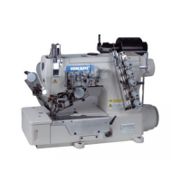
| Model | HW762T |
| Category | Sewing Machine |
| Language | English |