Digital Video Recorder Quick Start Guide
16
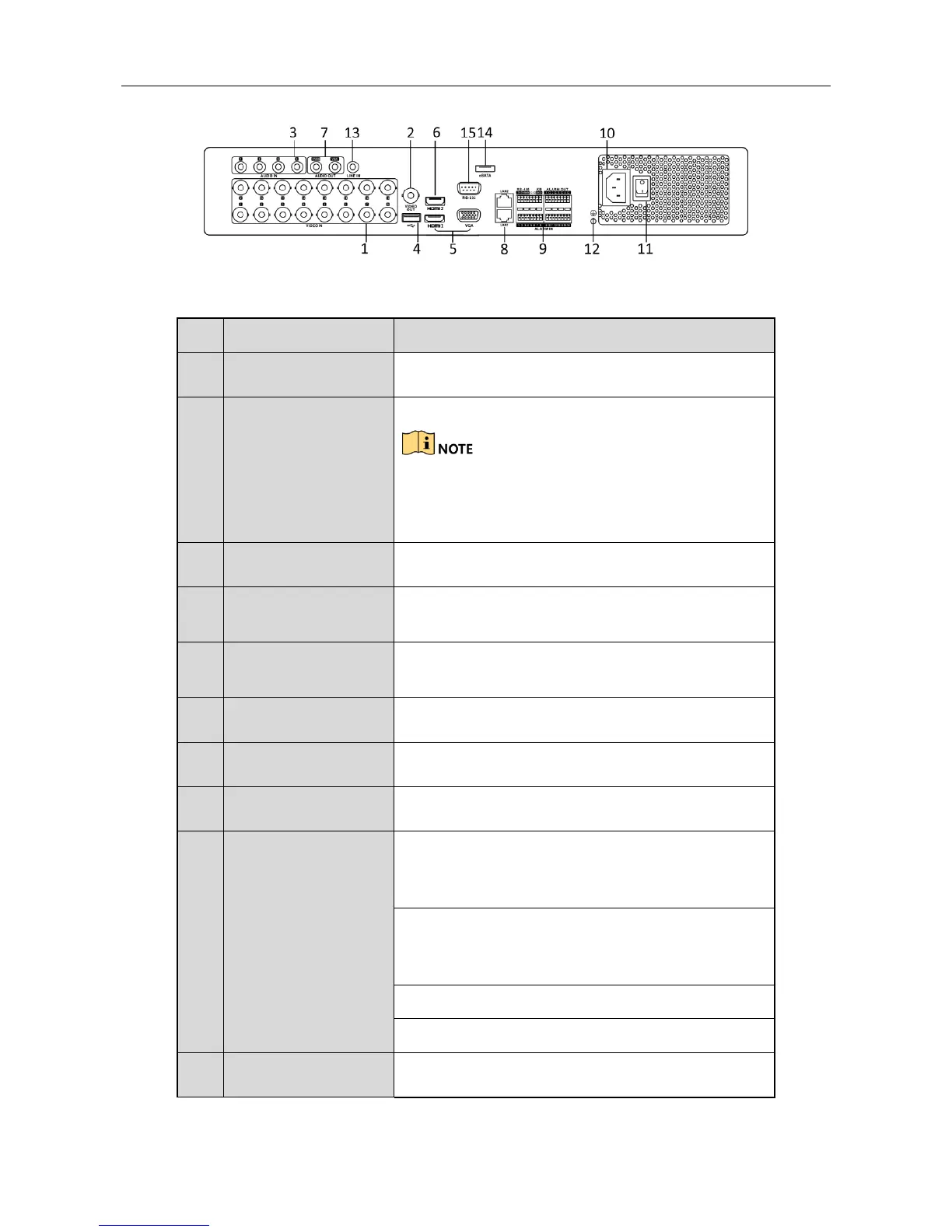
Figure 1-7 Rear Panel 2
Table 1-6 Description of Rear Panel 2
BNC interface for TVI and analog video input.
BNC connector for video output.
CVBS output is not provided for DS-7100/7200HGHI-E1,
DS-7200HGHI-E2, DS-7100/7200HGHI-F1,
DS-7200HGHI-F2, DS-7100HQHI-F1/N and
DS-7100HGHI-F1/N series DVR.
Universal Serial Bus (USB) port for additional
devices.
Simultaneous HDMI1/VGA output. Display local
video output and menu.
HDMI2 video output connector.
RS-485 and Alarm
Interface
Connector for RS-485 devices. T+ and T- pins
connect to R+ and R- pins of PTZ receiver
respectively.
D+, D- pin connects to Ta, Tb pin of controller. For
cascading devices, the first DVR’s D+, D- pin should
be connected with the D+, D- pin of the next DVR.
Connector for alarm input.
Connector for alarm output.
100 to 240V AC power supply.
 Loading...