2 Terminal and Wiring Descripon
2.1 Terminal Descripon
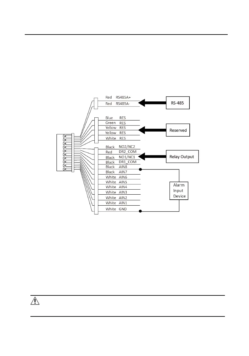
There are 20 pins in the terminal on the rear panel of the indoor staon: 2 RS-485
pins, 5 reserved pins, 4 relay output pins, 8 alarm input pins, and 1 GND pin.
Figure 2-1 Terminal Descripon
2.2 Wiring
Descripon
Wire the devices with power supply cables as picture shown below.
Door staon should be connected to CH6 of the video/audio distributor with two-
wire cables.
Indoor Staon should be connected to any terminal of CH1 to CH5 of the video/
audio distributor with two-wire cables.
Cauon
Make sure all the related equipment is power-o during the installaon.
Network Indoor Staon Installaon Guide
3
 Loading...