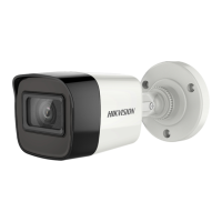
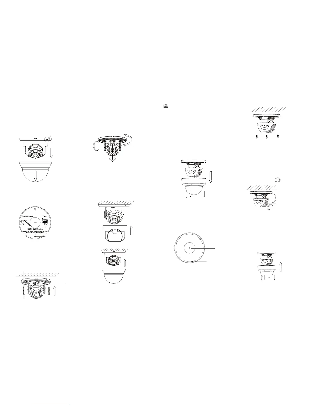
2.2 Installation of Type CameraII
3.Align the base plate with the mounting template
and secure it with supplied self-tapping screws.
4. Route the cables through the cable hole.
5. Connect the corresponding cables.
6. Adjust the camera according to the figure below
to get an optimum angle.
7. Push the black liner and bubble toward the
camera and buckle them upon to secure them
on the camera.
Base Plate
P Direction
0 ~350°°
0~70°°
T Direction
Figure 2-4 3-axis Adjustment
Figure 2-5 Complete the Installation
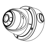
1.Loosen the screws on the bubble to remove the
bubble and the black liner.
Figure 2-6 Remove the Bubble
2.Drill the screw holes and cable hole on the
ceiling according to the supplied drill template.
Drill Template
Hole A: for cables routed through the ceiling
screw hole 1: for Mounting Base
1
1
1
A
Figure 2-7 Drill Template
Screw Hole
Cable Hole
3.Align the base plate with the mounting template
and secure it with supplied self-tapping screws.
4. Route the cables through the cable hole.
5. Connect the corresponding cables.
6. Adjust the camera according to the figure below
to get an optimum angle.
Figure 2-8 Fix the Camera to the Ceiling
8. Fit the black liner and bubble on the camera.
R Direction
0~75°°
P Direction
0 ~355°°
T Direction
Adjustment
Screw
Figure 2-9 3-axis Adjustment
Figure 2-10 Complete the Installation
0 ~350°°
R Direction
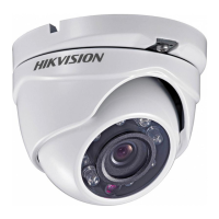
2.1 Installation of Type CameraI
2.Drill the screw holes and cable hole according to
the drill template.
Figure 2-2 The Drill Template
Screw Hole
1.Pry the snap joint up to remove the bubble
and the black liner.
Cable Hole
Snap Joint
Figure 2-1 Remove the Bubble
Steps:
Rotate the bubble after completing the
Installation may change the postion of the lens.
0 ~355°°
 Loading...