Do you have a question about the hilscher CIFX Series and is the answer not in the manual?
Describes the scope and content of the user manual for PC cards cifX.
Details the changes and updates across different document sections and versions.
Provides compatibility information and version details for hardware, firmware, software, and drivers.
Lists hardware revisions, part numbers, and DMA mode support for PC Cards cifX.
Details basic cards and detached network interfaces (AIFX) for PC Cards cifX.
Lists firmware files and their corresponding versions for various protocols.
Lists software components like SYCON.net, driver setup, and toolkit versions.
Explains symbols and formatting used in the manual for notes and instructions.
Defines key terms and abbreviations used throughout the manual.
Outlines the contents of the Communication Solutions DVD, including software and documentation.
Guides on locating installation instructions and documentation overview on the DVD.
Points to the location of version information for hardware and software updates.
Highlights significant modifications in firmware versions, such as DeviceNet Master firmware updates.
Discusses the revision, features, and upgrade recommendations for PROFINET IO-Controller firmware.
Explains the role of device description files (EDS, GSD, XDD) for configuring master devices.
Contains copyright information, disclaimers, and notes on usage and liability.
Lists registered trademarks for operating systems, software, and technologies used.
Provides disclaimer and reference documents for EtherCAT technology usage.
Emphasizes the importance of reading the manual for safety and proper operation.
Explains license requirements for firmware with master functionality.
General safety advice, stressing adherence to regulations and personnel knowledge.
Describes the purpose of PC cards cifX for Real-Time Ethernet and fieldbus communication.
Specifies the required qualifications for installing, configuring, and removing PC cards cifX.
Stresses reading and complying with all safety instructions before installation and operation.
Warns about hazardous voltage and precautions for electrical shock prevention.
Warns about communication interruption and potential data loss during firmware/configuration updates.
Alerts to potential issues from incorrect system configurations leading to unexpected operation.
Advises to read instructions to avoid system and device damage to PC card cifX.
Warns about potential damage from incorrect supply voltage levels and specifies requirements.
Alerts about potential device damage due to exceeding specified signaling voltage limits.
Provides precautions for handling ESD-sensitive components to prevent damage.
Warns about consequences of power loss during downloads, like corruption or damage.
Explains the limit on flash chip write/delete accesses to prevent device damage.
Warns that loading invalid firmware can render the device unusable.
Advises on security measures for devices with Ethernet access to public networks.
Explains signal words and safety signs used to indicate types of hazards.
Lists safety standards and references used in the document.
Introduces PC cards cifX as communication interfaces based on netX 100.
Details PC cards with integrated Ethernet, fieldbus, or diagnostic interfaces.
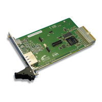
Describes Compact PCI cards cifX 80-XX and their integrated interfaces.
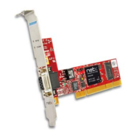
Details PCI-104 cards with integrated interfaces for Ethernet, fieldbus, and diagnostics.
Explains PC cards combined with detached network interfaces (AIFX) via cable connectors.
Explains the "\F" label indicating a basic card with a detached network interface.
Details Mini PCI cards cifX 90-XX\F and their variants with detached network interfaces.
Describes Mini PCI Express cards cifX 90E-XX\F and their variants with detached network interfaces.
Details Mini PCI Express cards cifX 90E-XX\NHS\F and variants with detached network interfaces.
Describes Mini PCI Express cards cifX 90E-XX\ET\F and variants with detached network interfaces.
Details Mini PCI Express cards cifX 90E-XX\MR\F and variants with detached network interfaces and MRAM.
Describes Mini PCI Express cards with MRAM, enlarged temperature range, and detached interfaces.
Details 2-channel Mini PCI Express cards for Real-Time Ethernet with enlarged temperature range.
Describes 2-channel Mini PCI Express cards with MRAM and enlarged temperature range.
Details PCI-104 cards with detached network interfaces for Ethernet and fieldbus.
Lists all detached network interfaces (AIFX) and the corresponding PC Cards cifX they support.
Explains the DMA mode functionality and its activation via the device driver.
Lists required firmware, driver, and SYCON.net setup versions for DMA Mode.
Describes PC cards equipped with additional MRAM for remanent data storage.
Outlines system requirements including slot types and bus specifications for PC cards.
Specifies the required PCI bus slots (Compact PCI, Mini PCI, Mini PCIe, PCI-104) for different card types.
Provides notes on card height dimensions and cable connector heights for Mini PCI and Mini PCIe cards.
Details the required panel cutouts and holes for installing detached network interfaces (AIFX).
Specifies operating temperature ranges for UL certificates and device design.
Outlines requirements for power supply and host interfaces (Compact PCI, Mini PCI, Mini PCIe, PCI-104).
Lists essential requirements for proper operation, including driver, software, and firmware.
Lists prerequisites for PROFINET IO certification, focusing on SYNC0 signal.
Details requirements for PROFINET IO certification related to SYNC0 signal provision and usage.
Presents critical warnings regarding personal injury and property damage during installation.
Provides a step-by-step guide for software and hardware installation, and configuration.
Important note on manually downloading firmware and configuration for replacement cards.
Provides specific notes for configuring master devices for various communication systems.
Explains the process for updating firmware, drivers, and software, emphasizing project file backup.
Provides device drawings and front panel views for Compact PCI PC Cards cifX.
Shows the layout and connectors for the CIFX 80-RE Compact PCI card.
Displays device drawings and front panel views for the CIFX 80-DP Compact PCI card.
Shows device drawings and front panel views for the CIFX 80-CO Compact PCI card.
Provides device drawings and front panel views for the CIFX 80-DN Compact PCI card.
Presents device drawings for Mini PCI and Mini PCI Express cards.
Shows drawings of basic cards CIFX 90 and CIFX 90E for RE\F and RE\F\M12 variants.
Displays drawings for Mini PCI and Mini PCI Express cards with FB variants.
Shows drawings for 2-channel Mini PCI Express cards with ET and MR\ET variants.
Illustrates the reverse side of CIFX 90-XX\F and CIFX 90E-XX\F cards.
Provides device drawings for PCI-104 cards.
Shows drawings and connector assignments for CIFX 104C-RE and CIFX 104C-RE-R PCI-104 cards.
Displays drawings for CIFX 104C-RE\F and CIFX 104C-RE-R\F variants with diagnostic interfaces.
Shows drawings and connector assignments for CIFX 104C-DP and CIFX 104C-DP-R PCI-104 cards.
Displays drawings and connector assignments for CIFX 104C-CO and CIFX 104C-CO-R PCI-104 cards.
Shows drawings and connector assignments for CIFX 104C-DN and CIFX 104C-DN-R PCI-104 cards.
Details PCI-104 cards with Fieldbus interfaces and detached network interfaces.
Shows PCI-104 cards with Fieldbus interfaces and detached network interfaces, right-side connectors.
Illustrates the reverse side of CIFX 104C-XX PCI-104 cards.
Provides drawings for detached network interfaces (AIFX).
Shows dimensioning and connector details for the AIFX-RE Ethernet interface.
Displays dimensioning and connector details for the AIFX-RE\M12 Ethernet interface.
Shows dimensioning and connector details for the AIFX-DP PROFIBUS interface.
Displays dimensioning and connector details for the AIFX-CO CANopen interface.
Shows dimensioning and connector details for the AIFX-DN DeviceNet interface.
Displays dimensioning and connector details for the AIFX-CC CC-Link interface.
Shows dimensioning and connector details for the AIFX-DIAG diagnostic interface.
Instructions for applying front plate stickers to CIFX 80-RE based on firmware.
Step-by-step guide for installing Compact PCI cards, including safety precautions.
Step-by-step guide for uninstalling Compact PCI cards, including safety precautions.
Guide for installing Mini PCI and Mini PCI Express cards, including safety and mounting.
Step-by-step guide for uninstalling Mini PCI and Mini PCI Express cards.
Guide for installing PCI-104 modules, including safety and connection of AIFX interfaces.
Step-by-step guide for uninstalling PCI-104 cards and their detached network interfaces.
Provides guidance for solving problems by examining LEDs, cables, configurations, and diagnostics.
Explains the function and states of LEDs for various Real-Time Ethernet systems.
Describes the function and states of LEDs for various Fieldbus systems.
Details the states and meanings of the System Status LED (SYS) for devices.
Explains the states and meaning of the Power On LED (PWR) indicating power supply status.
Describes the LED states for the CC-Link IE Field Basic Slave protocol.
Explains LED states for EtherCAT Master protocol (V3), including RUN, ERR, LINK, ACT LEDs.
Details LED states for EtherCAT Master protocol (V4), covering RUN, ERR, LINK, ACT LEDs.
Explains LED states for EtherCAT Slave protocol, including RUN, ERR, L/A IN/OUT LEDs.
Describes LED states for EtherNet/IP Scanner (Master) protocol (MS, NS, LINK, ACT).
Explains LED states for EtherNet/IP Adapter (Slave) protocol (MS, NS, LINK, ACT).
Details LED states for the Open Modbus/TCP protocol, including RUN, ERR, LINK, ACT LEDs.
Explains LED states for POWERLINK Controlled Node/Slave protocols (BS, BE, L/A).
Describes LED states for PROFINET IO-Controller V2 protocol (SF, BF, LINK, RX/TX).
Details LED states for PROFINET IO Controller V3 protocol (SYS, SF, BF, LINK, RX/TX).
Explains LED states for PROFINET IO-Device V3.13 protocol (SF, BF, LINK, RX/TX).
Describes LED states for the Sercos Master protocol (STA, ERR, L/A).
Explains LED states for the Sercos Slave protocol (S, L/A).
Details LED states for the VARAN Client (Slave) protocol (RUN, ERR, LINK, ACT).
Provides details on PROFIBUS DP Master protocol status LEDs.
Explains the states of the single communication status LED (COM) for PROFIBUS DP Master.
Details the states of the two communication status LEDs (STA, ERR) for PROFIBUS DP Master.
Provides details on PROFIBUS DP Slave protocol status LEDs.
Explains the states of the single communication status LED (COM) for PROFIBUS DP Slave.
Details the states of the two communication status LEDs (STA, ERR) for PROFIBUS DP Slave.
Provides details on PROFIBUS MPI Device protocol status LEDs.
Explains the states of the single communication status LED (COM) for PROFIBUS MPI Device.
Details the states of the two communication status LEDs (STA, ERR) for PROFIBUS MPI Device.
Provides details on CANopen Master protocol status LEDs.
Explains the states of the single communication status LED (CAN) for CANopen Master.
Details the states of the two communication status LEDs (RUN, ERR) for CANopen Master.
Provides details on CANopen Slave protocol status LEDs.
Explains the states of the single communication status LED (CAN) for CANopen Slave.
Details the states of the two communication status LEDs (RUN, ERR) for CANopen Slave.
Provides details on DeviceNet Master protocol status LEDs.
Explains the states of MS and NS LEDs for DeviceNet Master protocol.
Details the states of the MNS LED for DeviceNet Slave protocol.
Details the states of the MNS LED for DeviceNet Slave protocol.
Explains the LED states for the CC-Link Slave protocol (L-RUN, L-ERR).
Describes the Ethernet interface using RJ45 or M12 connectors and cable requirements.
Details the pin assignment for the RJ45 Ethernet socket on cifX or AIFX.
Provides the pin assignment for the M12 Ethernet socket on AIFX-RE\M12.
Lists technical data for Ethernet connections, including medium, length, and transmission rate.
Specifies the acceptable use of hubs and switches for various communication systems.
Details the PROFIBUS interface (DSub female connector) and its pin assignment.
Describes the CANopen interface (DSub male connector) and its pin assignment.
Provides details for the DeviceNet interface (CombiCon male connector) and its pin assignment.
Details the CC-Link interface (CombiCon male connector) and its pin assignment.
Details the pin assignment for the Mini-B USB connector used on various PC cards and AIFX.
Explains the use and settings of the rotary switch for PCI-104 slot numbering.
Notes that the device address rotary switch is currently unassigned and configured via software.
Introduces cable connectors and their pin assignments.
Details the pin assignment for Ethernet cable connectors X4 or X304.
Provides pin assignments for fieldbus cable connectors X3, X304, and X4 for single-channel devices.
Details pin assignments for fieldbus cable connectors X3 and X4 for 2-channel devices.
Details pin assignments for the DIAG cable connector X3 or X303.
Provides pin assignments for the Ethernet cable connector X2 on the AIFX-RE\M12 interface.
Details pin assignments for LED signals via cable connector X3 on the AIFX-RE\M12.
Lists available cables for detached network interfaces like AIFX-RE and AIFX-RE\M12.
Specifies part numbers and lengths for AIFX-RE and AIFX-RE\M12 cables.
Details the SYNC connector pin assignments and hardware/firmware items.
Shows the pin assignment for the SYNC connector X51 on CIFX 80, 90, and 104C cards.
Provides an overview of PCI bus pin assignments for various cifX cards.
Offers a summary of PCI bus types, pins, and corresponding sections for pin assignments.
Lists relevant PCI specifications and their sources for reference.
Details the pin assignment for the Mini PCI Bus, X1 connector.
Details pin assignments for Mini PCI Express Bus and SYNC Connector (X1/X2) for earlier hardware revisions.
Details pin assignments for Mini PCI Express Bus X1/X2 for 2-channel devices.
Provides technical specifications for PC Cards cifX.
Details technical specifications for the CIFX 80-RE PC card, including communication, interface, and environmental data.
Provides technical specifications for the CIFX 80-DP PC card, including PROFIBUS interface.
Details technical specifications for the CIFX 80-CO PC card, including CANopen interface.
Provides technical specifications for the CIFX 80-DN PC card, including DeviceNet interface.
Details technical specifications for CIFX 90E-RE\F and variants, including MRAM and Ethernet interfaces.
Provides technical specifications for CIFX 90E-DP\F and variants, including PROFIBUS interface and MRAM.
Details technical specifications for CIFX 90E-CO\F, including CANopen interface and MRAM.
Provides technical specifications for CIFX 90E-DN\F, including DeviceNet interface and MRAM.
Details technical specifications for CIFX 90E-CC\F, including CC-Link interface and MRAM.
Details technical specifications for CIFX 90E-RE\F and variants, including MRAM and Ethernet interfaces.
Provides technical specifications for CIFX 90E-DP\F and variants, including PROFIBUS interface and MRAM.
Details technical specifications for CIFX 90E-CO\F and variants, including CANopen interface and MRAM.
Provides technical specifications for CIFX 90E-DN\F and variants, including DeviceNet interface and MRAM.
Details technical specifications for CIFX 90E-CC variants with CC-Link interface and MRAM.
Provides technical specifications for 2-channel CIFX 90E DP cards with ET/MR\ET variants, PROFIBUS interface.
Details technical specifications for 2-channel CIFX 90E DP/CO cards with ET/MR\ET variants, PROFIBUS/CANopen interfaces.
Provides technical specifications for 2-channel CIFX 90E DP/DN cards with ET/MR\ET variants, PROFIBUS/DeviceNet interfaces.
Details technical specifications for 2-channel CIFX 90E CO cards with ET/MR\ET variants, CANopen interface.
Provides technical specifications for 2-channel CIFX 90E CO/DN cards with ET/MR\ET variants, CANopen/DeviceNet interfaces.
Details technical specifications for 2-channel CIFX 90E DN cards with ET/MR\ET variants, DeviceNet interface.
Provides technical specifications for PCI-104 CIFX 104C-RE and RE-R cards, including Ethernet interface.
Details technical specifications for PCI-104 CIFX 104C-RE\F and RE-R\F variants with Ethernet and diagnostic interfaces.
Provides technical specifications for PCI-104 CIFX 104C-DP and DP-R cards, including PROFIBUS interface.
Details technical specifications for PCI-104 CIFX 104C-DP\F and DP-R\F variants with PROFIBUS and diagnostic interfaces.
Provides technical specifications for PCI-104 CIFX 104C-CO and CO-R cards, including CANopen interface.
Details technical specifications for PCI-104 CIFX 104C-CO\F and CO-R\F variants with CANopen and diagnostic interfaces.
Provides technical specifications for PCI-104 CIFX 104C-DN and DN-R cards, including DeviceNet interface.
Details technical specifications for PCI-104 CIFX 104C-DN\F and DN-R\F variants with DeviceNet and diagnostic interfaces.
Provides technical specifications for PCI-104 CIFX 104C-CC\F, including CC-Link interface and diagnostic interface.
Details technical specifications for the AIFX-RE detached Ethernet network interface.
Provides technical specifications for the AIFX-RE\M12 detached Ethernet network interface.
Details technical specifications for the AIFX-DP detached PROFIBUS network interface.
Provides technical specifications for the AIFX-CO detached CANopen network interface.
Details technical specifications for the AIFX-DN detached DeviceNet network interface.
Provides technical specifications for the AIFX-CC detached CC-Link network interface.
Details technical specifications for the AIFX-DIAG detached diagnostic interface.
Lists the PCI Vendor ID, Device ID, and Subsystem IDs for PC Cards cifX.
Shows which PCI bus commands are supported by the PC Cards cifX.
Provides technical data for various communication protocols.
Lists technical data for the CC-Link IE Field Basic Slave protocol.
Provides technical data for the EtherCAT Master (V3) protocol.
Lists technical data for the EtherCAT Master (V4) protocol, including slave limits and bus cycle times.
Provides technical data for the EtherCAT Slave protocol, including cyclic data limits and FMMUs.
Lists technical data for the EtherNet/IP Scanner (Master) protocol, including connections and objects.
Provides technical data for the EtherNet/IP Adapter (Slave) protocol, including connection types and baud rates.
Lists technical data for the Open Modbus/TCP protocol, including function codes and protocol modes.
Provides technical data for POWERLINK Controlled Node/Slave (V2) protocol.
Lists technical data for POWERLINK Controlled Node/Slave (V3) protocol.
Provides technical data for PROFINET IO-Controller (V2) protocol, including device limits and functions.
Lists technical data for PROFINET IO-Controller (V3) protocol, including AR limits and DCP functions.
Provides technical data for PROFINET IO-Device (V3.13) protocol, including submodule limits and supported protocols.
Lists technical data for the Sercos Master protocol, including slave devices and communication phases.
Provides technical data for the Sercos Slave protocol, including slave devices and communication phases.
Lists technical data for the VARAN Client (Slave) protocol, including memory area and limitations.
Provides technical data for the PROFIBUS DP Master protocol, including slave limits and baud rates.
Lists technical data for the PROFIBUS DP Slave protocol, including cyclic data limits and baud rates.
Provides technical data for the PROFIBUS MPI protocol, including connection limits and baud rates.
Lists technical data for the CANopen Master protocol, including node limits and baud rates.
Provides technical data for the CANopen Slave protocol, including cyclic data limits and baud rates.
Lists technical data for the DeviceNet Master protocol, including slave limits and connection types.
Provides technical data for the DeviceNet Slave protocol, including cyclic data limits and baud rates.
Lists technical data for the CC-Link Slave protocol, including station types and baud rates.
Explains how to identify devices using matrix or bar codes on the label.
Details manufacturing tolerances for printed circuit board dimensions of PC cards.
Provides dimensional drawings for CIFX 80-RE Compact PCI cards.
Shows the dimensions of the CIFX 80-RE Compact PCI card.
Displays the front panel dimensions for the CIFX 80-RE card.
Shows the dimensions of the CIFX 80-DP Compact PCI card.
Details the dimensions of the CIFX 80-CO Compact PCI card.
Displays the front panel dimensions for the CIFX 80-CO card.
Shows the dimensions of the CIFX 80-DN Compact PCI card.
Displays the front panel dimensions for the CIFX 80-DN card.
Provides dimensional drawings for Mini PCI and Mini PCI Express cards.
Shows the dimensions of CIFX 90-XX\F Mini PCI cards and variants.
Provides dimensional drawings for PCI-104 cards.
Shows the dimensions of the CIFX 104C-RE PCI-104 card.
Displays the dimensions of the CIFX 104C-RE\F PCI-104 card.
Shows the dimensions of the CIFX 104C-DP PCI-104 card.
Details the dimensions of the CIFX 104C-CO PCI-104 card.
Shows the dimensions of the CIFX 104C-DN PCI-104 card.
Details the dimensions of the CIFX 104C-FB\F PCI-104 card.
Illustrates the reverse side of CIFX 104C-XX PCI-104 cards.
Provides dimensioning drawings for detached network interfaces (AIFX).
Shows the dimensions of the AIFX-RE Ethernet detached network interface.
Displays dimensioning for the AIFX-RE\M12 Ethernet M12 detached network interface.
Shows dimensioning for the AIFX-DP PROFIBUS detached network interface.
Displays dimensioning for the AIFX-CO CANopen detached network interface.
Shows dimensioning for the AIFX-DN DeviceNet detached network interface.
Displays dimensioning for the AIFX-CC CC-Link detached network interface.
Shows dimensioning for the AIFX-DIAG diagnostic detached network interface.
Details issues and workarounds for earlier hardware revisions, specifically 10 MBit/s Half Duplex mode.
Details pin assignments for Mini PCI Express Bus and SYNC Connector (X1/X2) for earlier hardware revisions.
Provides information on the proper disposal of waste electronic equipment according to WEEE directive.
Lists references to protocol API manuals and other relevant documentation.
Summarizes EtherCAT vendor ID, conformance testing, and logo usage policies.
Explains the use and replacement of vendor IDs for EtherCAT products.
Details EtherCAT conformance requirements and testing policies.
Discusses the difference between certified products and network interfaces for EtherCAT.
Lists all figures with their corresponding page numbers for easy reference.
Provides definitions for technical terms and abbreviations used in the manual.
| Manufacturer | Hilscher |
|---|---|
| Product Series | CIFX |
| Category | Communication Interface Cards |
| Supported Networks | PROFIBUS, PROFINET, DeviceNet, CANopen, EtherNet/IP, CC-Link, SERCOS III, Modbus TCP |
| Form Factor | PCI, CompactPCI, Mini PCIe |
| Operating System Support | Windows, Linux, QNX, VxWorks |
| Interface | PCI, CompactPCI, Mini PCIe |
| Operating Temperature | 0°C to +60°C |
| Certifications | CE, UL, RoHS |