IRIS2 - User manual
Feeding 12Vdc
BURGLARY CENTRAL
UNITS
IRIS2
OPERATION
This function prevents to put the sensor out of use masking only one of the two technologies of movement detection and protects the detector by possible housebreaking.
IMPULSE-COUNTER
! If the number of impulses is programmed to one, the detector enables immediately also the OUT output (contacts opening)
and signals the detection also to the antitheft control station
! If the number of programmed impulses is greater than one, the red LED signals with a flash the first detection then remains interdicted for approx two seconds.
! If the movement detection status persists or a new one occurs within the subsequent 15 seconds the red LED repeats the signalling.
Every flash by the RED LED (it means every Microwave + PIR detection, only Microwave or only PIR) is counted. When the level set on the impulse-counter is exceeded
the RED LED turns on and the relay excites generating the alarm.
NOTE: After 15 seconds from a detection, the impulse counter resets.
When the number of impulse signalling achieves the programmed number, the red LED turns on with fixed light and the OUT contact is open to signal the
alarm to the antitheft control station.
SWITCH1/SWITCH2 To position the dip-switch according to the wished value:
NOTE: After 15 seconds from a detection, the impulse counter resets.
SIGNALLING LED EXCLUSION
Turning the dip switch 4 on ON (SW=ON) the detection and alarm signals of the LEDs are disabled. The only signalling still active are the initial flashing in the detector
turn-on phase and the flashing for the memory input activation.
! ALARM MEMORY
This function allows to identify which detector has generated an alarm.
To enable the alarm memory, connect the input “M” to the output “+INT” of the antitheft control station.
Red LED operation (alarm memory)
! Slow flashing (5 sec.): insertion.
! Quick flashing: signalling of the sensor detection with active alarm memory.
! Acceso fisso: Fixed light: signalling of the sensor detection without active alarm memory.
NOTE The alarm memory cancellation occurs automatically after 5 seconds from the system insertion. The activation occurs after 15 seconds of delay from the system
insertion.
EMPLOYMENT
Applying voltage to the detector, the RED LED starts flashing for a minute to allow the stabilization of the infrared sensor
:
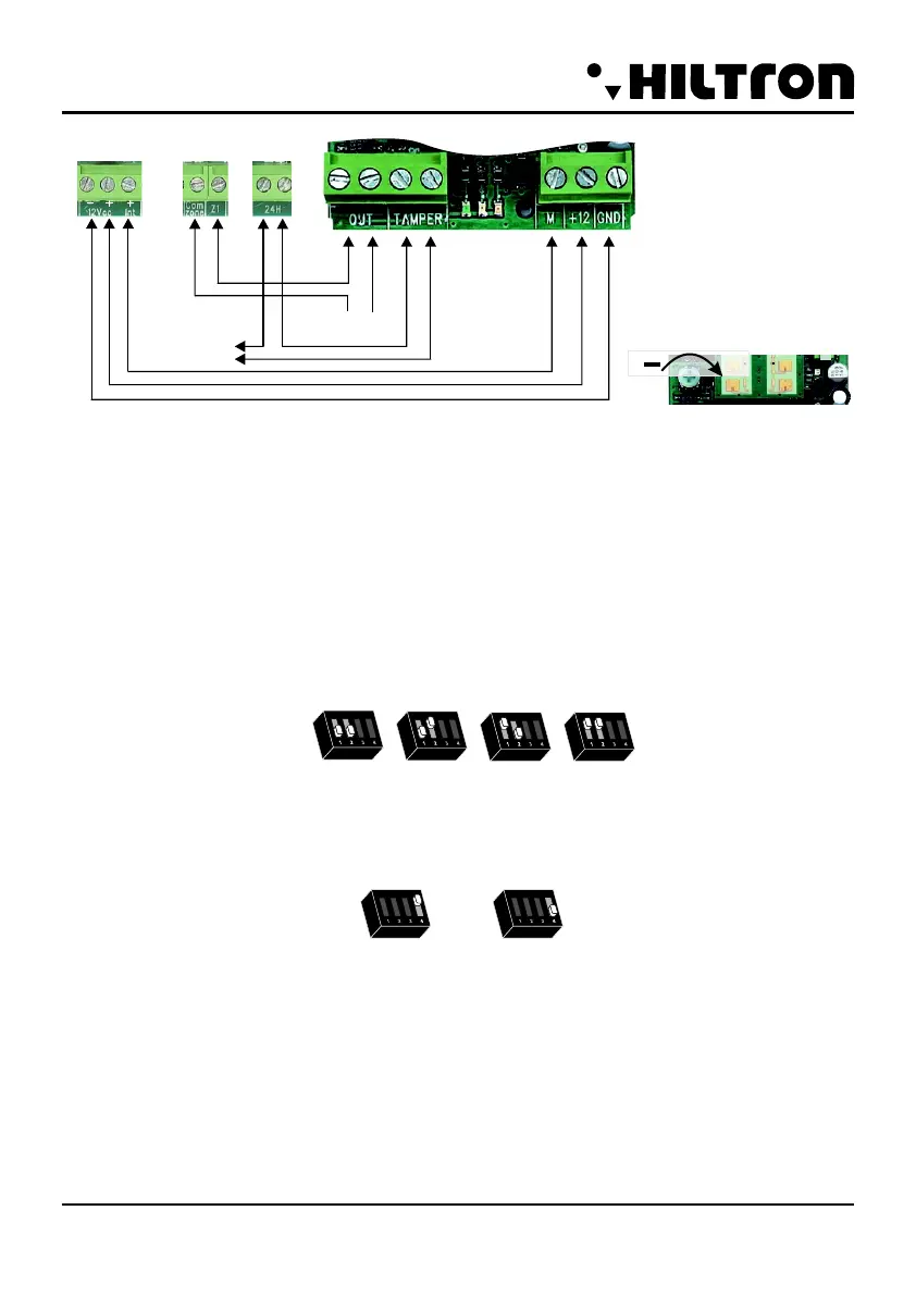
ON
SW1=OFF
SW2=OFF
1 Impulses
ON
SW1=OFF
SW2=ON
2 Impulses
ON
SW1=ON
SW2=OFF
3 Impulses
ON
SW1=ON
SW2=ON
4 Impulses
SW4=ON
(activated exclusion)
ON
SW4=OFF
(disactivated exclusion
ON
IRIS2 - User manual
Feeding 12Vdc
BURGLARY CENTRAL
UNITS
IRIS2
OPERATION
This function prevents to put the sensor out of use masking only one of the two technologies of movement detection and protects the detector by possible housebreaking.
IMPULSE-COUNTER
! If the number of impulses is programmed to one, the detector enables immediately also the OUT output (contacts opening)
and signals the detection also to the antitheft control station
! If the number of programmed impulses is greater than one, the red LED signals with a flash the first detection then remains interdicted for approx two seconds.
! If the movement detection status persists or a new one occurs within the subsequent 15 seconds the red LED repeats the signalling.
Every flash by the RED LED (it means every Microwave + PIR detection, only Microwave or only PIR) is counted. When the level set on the impulse-counter is exceeded
the RED LED turns on and the relay excites generating the alarm.
NOTE: After 15 seconds from a detection, the impulse counter resets.
When the number of impulse signalling achieves the programmed number, the red LED turns on with fixed light and the OUT contact is open to signal the
alarm to the antitheft control station.
SWITCH1/SWITCH2 To position the dip-switch according to the wished value:
NOTE: After 15 seconds from a detection, the impulse counter resets.
SIGNALLING LED EXCLUSION
Turning the dip switch 4 on ON (SW=ON) the detection and alarm signals of the LEDs are disabled. The only signalling still active are the initial flashing in the detector
turn-on phase and the flashing for the memory input activation.
! ALARM MEMORY
This function allows to identify which detector has generated an alarm.
To enable the alarm memory, connect the input “M” to the output “+INT” of the antitheft control station.
Red LED operation (alarm memory)
! Slow flashing (5 sec.): insertion.
! Quick flashing: signalling of the sensor detection with active alarm memory.
! Acceso fisso: Fixed light: signalling of the sensor detection without active alarm memory.
NOTE The alarm memory cancellation occurs automatically after 5 seconds from the system insertion. The activation occurs after 15 seconds of delay from the system
insertion.
EMPLOYMENT
Applying voltage to the detector, the RED LED starts flashing for a minute to allow the stabilization of the infrared sensor
:
ON
SW1=OFF
SW2=OFF
1 Impulses
ON
SW1=OFF
SW2=ON
2 Impulses
ON
SW1=ON
SW2=OFF
3 Impulses
ON
SW1=ON
SW2=ON
4 Impulses
SW4=ON
(activated exclusion)
ON
SW4=OFF
(disactivated exclusion
ON
+
Regulation sensibility
In series to
other contacts or
detectors NC
In series
to the line
24h
Activation Memory Alarm
IRIS2
Detecteur volumétrique double IR portée élargie
!
!
!
!
!
!
!
!
!
!
!
!
!
!
!
!
!
!
!
!
!
!
Le detecteur volumétrique IRIS est composé avec un ensamble de circuits réalisé en technologie SMT pour assurer une plus haute stabilité en phase d’utilisation et
une plus grande immunité contre les bruillages électromagnétiques.
La possibilité de régler la sensibilité permet d’installer cet dispositif en n’importe quelle pièce où soit necessaire une protetion volumétrique discrète et sûre.
La fonction "Memoire Alarme" signalée par le LED permet de quand differents detecteurs sont installés en série
; la connexion de la tension (+12V Int.) de la centrale, permettra d’annuler telle signalisation avec chaque activation de l'installation antivol.
Capteur digital à double element (Digipyro™): 2
Équipé de joint d'anti-disorentation
Bloc de fermature par vis
Memoire alarme par signalisation locale l'exclure
Fonction "Compteur d'implusions" avec reset
Niveaux de sensibilité settables: 4
Tamper de protection anti-ouverture
Immunité élevée à RF: 30Vm
Tension nominale d'alimentation:
Consommation maximale: 10mA
Rayons de la lentille: 17
Niveaux de la lentille: 3
Angle de couverture frontale (PIR): H: 120°; V: 60°
Angle de couverture anti-frottement (PIR): H: 85°; V: 60°
Champ d'activité: max. 15mt
LED de signalisation escludible
Sorties relais état solide NC 100mA, 50Vcc max: 1
Temps de stabilisation initiale: 60"
Température de fonctionnement: +5°C ÷ +40°C
Degré de sécurité 1
! Class environmental 2
Dimensions (L)x(A)X(H): 59x99x60
Conforme normes CEI EN 50131-1-1
connaître quel decteteur a causé l'alarme sur la
meme zone
12Vcc ±10%
(sur 3 niveau) + 3 (sur 1 niveau vertical)
INSTALLATION
! Après avoir percé le mur et placé la chevile, fixer la base de l'articulation. Vérifier que la base de l'articulation ait bien été fixée, et, que la surface du mur soit lisse et non
sujette à vibrations.
! Ouvrir le détecteur et fixer la base de l'articulation. Serrer la vis à l'intérieur de l'articulation après avoir orienté le détecteur.
REMARQUE: Ne jamais orienter le détecteur vers une fenêtre ou des objets susceptibles de produire des changements rapides de température, tels que des radiateurs
électriques, des climatiseurs, des flammes, etc… Eviter donc son installation en proximité de ces derniers.
! Effectuer les branchements selon le schéma ci-dessous:
M peut être branchée au +INT de la centrale d'alarme, dans le cas où l'on veut activer la fonction “Mémoire Alarmes”, le cas contraire, il est inutile de la brancher.
! ATTENTION: Ne jamais toucher les senseurs pyroélectriques avec les doigts!
! Refermer le panneau frontal de l'appareil, d'abord en l'insérant par le bas sur la lentille demi-sphérique puis en le faisant glisser vers le haut jusqu'au déclic ; ensuite
placer la vis de sécurité, voir illustration..
PIR anti-frottement
PIR frontale
12
mt 3 6 15
2,2
mt 3 6 15
FRANÇAIS
4
5
EMC/2006/95/CE
Made in Italy
Azienda con Sistema di
gestione per la Qualità
UNI EN ISO 9001:2000
Azienda con Sistema di
gestione per la Qualità
UNI EN ISO 9001:2000
Azienda con Sistema di
gestione per la Qualità
UNI EN ISO 9001:2000
Azienda con Sistema di
gestione per la Qualità
UNI EN ISO 9001:2000
Pb
Lead free
RoHS
compliant
Pb
Lead free
RoHS
compliant
Pb
Lead free
RoHS
compliant
Pb
Lead free
RoHS
compliant
RAEE
 Loading...