GENERAL INFORMATION
This remote control is design
ed to separately control your ceiling fan
speed and light brightness.
● The fan button will control the fan speed. (1 - LOW, 2, 3, 4 - High)
● The Light button to control the light dimmer or ON/OFF.
● The red indicator on the transmitter will light when the button is
pressed.
NOTE: When installing the remote control, be sure the
light switch is set to ON. .
Fig. 1
Fig. 2
INSTALLATION AND OPERATING
INSTRUCTIONS
1. INSTALLING RECEIVER IN THE CEILING FAN
A. Safety precautions:
WARNING: HIGH VOLTAGE! Household electrical power can
cause serious injury or death. Disconnect the power to the ceiling
fan by removing the fuse or switching the power off at the circuit
breaker.
B. Installing receiver in fan.:
1. Remove the ceiling fan canopy from the hanger bracket. (Fig. 1)
2. Disconnect the existing wiring between the ceiling fan and
supply at the electrical junction box. (Fig. 1)
3. Lay the black antenna wire on top of the receiver, and put the
receiver in the mounting bracket. (Fig. 1)
4. Make the connections as follows, using the wire nuts supplied:
(Fig. 2)
a. Make wire connections from the fan to the receiver unit.
● Connect one BLACK wire from the fan to BLACK wire from
the receiver.
● Connect one BLUE wire from the fan to BLUE wire from the
receiver.
● Connect one WHITE wire from the fan to WHITE wire from
the receiver.
● Connect one GREEN wires from the fan to ground wire (green
or bare copper) from the ceiling.
b. Make wire connections from the receiver to the ceiling.
● Connect one BLACK wire from the receiver to BLACK wire
from the ceiling.
● Connect one WHITE wire from the receiver to WHITE wire
from the ceiling.
If there are wires with different colors, have this unit installed
by a qualified electrician.
5. Push all connected wires up into junction box.
6. Reinstall the canopy on the hanger bracket.
7. Restore the electrical power.
RECEIVER
Receiver
Outlet box
Ceiling
BLUE
WH
WH
WH
BLK
BLK
BLK
House
supply
wire
House
supply
wire
GRN
GRN
GROUND
Fan
4 SPEED FAN & LIGHT REMOTE CONTROL
WITH SMART RECEIVER
INSTALLATION INSTRUCTIONS
Model: 980002
READ AND SAVE THESE INSTRUCTIONS
Black
Blue
White
Wire nuts
Screws
Canopy
Black
White
Receiver
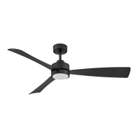
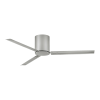
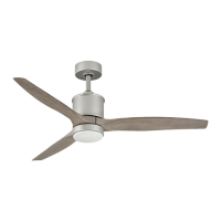
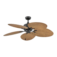
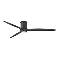
980002FBK-004: Gladiator 60" (900460)
980002FBK-004L: Gladiator Illuminated 60" (900460)
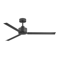
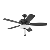
980002FBK-011:
Lafayette 52" (901152)
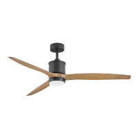
980002FBK-019:Tropic Air 52" (901952)
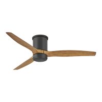
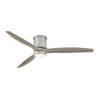
980002FBK-017L: Propel Illuminated 52" (901752)
Control is only compatible with the following Hinkley fans