Do you have a question about the Hinowa HP 1100 and is the answer not in the manual?
Location and marking of the CE plate.
Location of machine parts identification plates.
Explanation of safety warning signals used in the manual.
Meaning and usage of DANGER and WARNING messages.
Meaning and usage of IMPORTANT messages.
Pictogram indicating the need to consult the manual.
Pictogram warning about danger in the working area.
Pictogram for hydraulic oil filter.
Pictogram for hydraulic oil level.
General safety precautions and warnings.
Precautions to take before starting the engine.
Precautions to take while working with the machine.
Overview of driver's seat and controls for the standard version.
Overview of driver's seat and controls for the extensible version.
Controls and operation of the gasoline engine.
Controls and operation of the diesel engine.
Instructions for moving the minidumper.
How to operate the undercarriage for the standard version.
How to connect and operate external hydraulic tools.
How to operate the undercarriage for the extensible version.
How to operate the hydraulic tilting of the flat bed.
How to operate the extensible undercarriage features.
How to operate the second speed translation.
Usage of the optional control lever.
Precautions for manoeuvring on soft or unstable ground.
Warnings and precautions for operating on slopes.
Safe procedures for parking and stopping on slopes.
Instructions for safely transporting the machine.
General guidelines for maintenance procedures.
Procedures for maintaining the engine.
Procedures for maintaining the hydraulic system.
Checking and changing hydraulic oil.
Procedure for replacing the hydraulic oil filter.
Checking and changing reducer oil.
Checking battery electrolyte and terminals.
Procedures for maintaining rubber tracks.
How to check and adjust rubber track tension.
Procedures for loosening or tightening rubber tracks.
Visual inspection of rubber track condition.
Steps for replacing rubber tracks.
Steps for removing a rubber track.
Checking tightness of bolts and nuts.
Procedures for storing the machine.
Detailed technical data of the minidumper.
Diagram showing track dimensions and layout.
Hydraulic schematic for standard gasoline engine version.
Hydraulic schematic for extensible gasoline engine version.
Hydraulic schematic for standard diesel engine version.
Hydraulic schematic for extensible diesel engine version.
Troubleshooting steps when the engine does not start.
Troubleshooting when the carriage is not functioning correctly.
Troubleshooting low or no oil pressure issues.
Troubleshooting when there are no movements and the pump is noisy.
Troubleshooting issues related to lack of power in movements.
Troubleshooting joystick operational problems.
Image showing steel ropes that have been cut.
Image showing worn and broken steel cores.
Image showing steel core parting.
Image showing breaking of thread base due to rubber bending.
Image showing breaking of the tyre outer part.
Image showing breaking of the tyre inner part.
Image showing worn engraved thread on rubber tracks.
Image of rubber worn by driving wheels (first stage).
Image of rubber worn by driving wheels (final stage).
Image showing tyre cut from sharp material.
Image showing broken tyre outer part due to hard soil.
Image showing cut on tyre edge from sharp material.
Image showing tyre inner part breaking due to contact with frame.
| Brand | Hinowa |
|---|---|
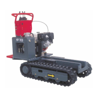
| Model | HP 1100 |
| Category | Lifting Systems |
| Language | English |