C
Christina WoodJul 25, 2025
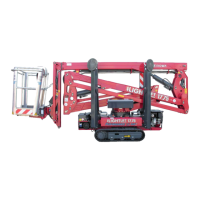
What to do if Hinowa LL2010 show a low battery level alarm?
- JJoel MartinJul 25, 2025
If you are experiencing a low battery level alarm on your Hinowa Boom Lifts, you should check the battery level and charge it if necessary.