8
Useful in preventive maintenance
8 channels alarm outputs
Motor speed, ow rate integration, etc.
8 channels pulse measurement
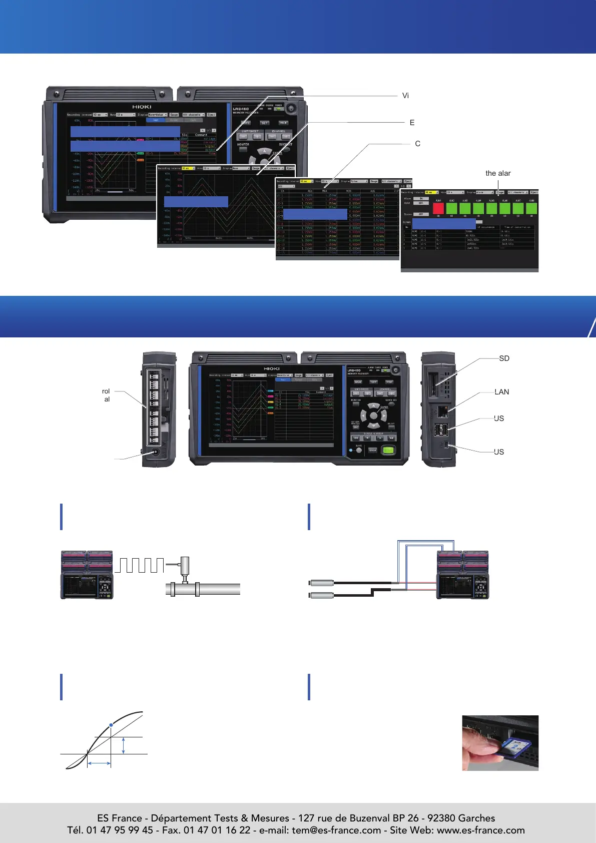
View waveforms and verify the numerical
values
Easy viewing of changes in waveforms
Check instantaneous, maximum, and
other values on a single screen
Check the alarm report
USB interface
(function)
USB interface
(host)
LAN interface
SD card slot
Easy-to-read display of measured values
Waveforms + numerical values
XY + numerical values
Waveforms
You can set alarm output for eight channels. You can
set a level, a window, a slope, and a logic pattern on
channels you wish to monitor.
Alarm
Input signals
Level
Time
Set the level and time.
It generates an alarm if the
reading exceeds the preset
rate of change (level/time)
Slope
External control
terminal
When you remove the storage media
while recording data, and reinsert it,
data remaining in the internal buffer
memory will continue to be stored in a
different le.
In "Revolve" mode, monitor production equipment by
measuring the variations in revolution speed of motors
or drills. In "Count" mode, identify operation status by
acquiring integrated power or ow rate.
The LR8450/LR8450-01 provides two output terminals for volt-
ages, each of which can supply 100 mA current, eliminating the
need for a separate sensor power supply. You can select 5 V,
12 V, or 24 V from the VOUTPUT1 terminal and 5 V or 12 V from
the VOUTPUT2 terminal.
Pulse signal
Use example:
Flow rate sensor
External control terminals and interfaces to accommodate a broad range of use cases
24 V
12 V
Sensor output voltage
Two terminals for voltage outputs (5, 12, or 24 V)
Supplying power to the sensors
Replace media during real-time saving
No need to stop recording
Power jack
Numerical values
Alarms
Use example:
Pressure transducer
ES France - Département Tests & Mesures - 127 rue de Buzenval BP 26 - 92380 Garches
Tél. 01 47 95 99 45 - Fax. 01 47 01 16 22 - e-mail: tem@es-france.com - Site Web: www.es-france.com

 Loading...


