Die separat verpackten
Befestigungsteile bereitlegen.
Bei Bohrungen mit
Ø 16,5 mm
sind die beiden
Stege an der Wippe abzu-
brechen.
Der Neigungswinkel ist
dann auf max. 26° einge-
schränkt.
Bei einer Bohrung von
Ø 20 - 22 mm sind die
Stege an der Wippe nicht
abzubrechen.
Der Neigungswinkel kann
dann bis zu 38° betragen.
Das HF- Anschlusskabel
(
➄
Fronteinbau,
➅
Heck-
einbau) am Antennenstutzen
anschrauben.
Die unteren Teile gemäß
Abbildung aufsetzen.
Die Antenne von unten in
die Karosserie einsetzen.
Die Wippe so drehen, daß
sie rund um die Bohrung
anliegt.
Die Halbkugel mit der Dicht-
unterlage von oben durch
die Bohrung in der auf der
Unterseite anliegenden
Wippe einfügen.
Die Halbschale und die
Mutter aufsetzen. Die Mut-
ter leicht anziehen.
Weitere Antennenköpfe für
schmale Kotflügel bzw. Nei-
gung bis 68° können ver-
wendet werden (siehe Über-
sicht S.8).
Préparer les pièces de fixa-
tion emballées séparément.
Dans les perçages de
16,5 mm de Ø les deux
barrettes doivent être rom-
pues à la bascule.
L'inclinaison de la carros-
serie peut être max. 26°.
Dans les perçages de
20 - 22 mm de Ø les deux
barrettes à la bascule ne
doivent pas être rompues.
L'inclinaison de la carros-
serie peut être max. 38°.
Visser le câble de connexion
HF sur le manchon d'an-
tenne (
➄
montage à l'avant,
➅
montage à l'arrière).
Placer les pièces inférieures
selon illustration.
Introduisez l'antenne par le
bas dans l'orifice de la car-
rosserie et tournez la pièce
basculante jusqu'à ce
qu'elle épouse parfaitement
la paroi intérieure de l'orifice.
Mettez en place, par le haut,
la demi-spère et le joint et
ajustez-les, à travers l'orifice,
à la pièce basculante.
Glissez la demi-coquille et
l'ecrou sur l'antenne et ser-
rez légèrement.
Pour des têtes d'antennes
pour des ailes étroites ou
des inclinaisons jusqu'à 68°
voir tableau des têtes, p. 8.
De apart verpakte bevesti-
gingsonderdelen klaar leg-
gen.
Bij gaten met
Ø
16,5 mm dienen de twee
verbindingsstukken op de
kanteltoets afgebroken te
worden.
De hellingshoek is dan op
max. 26° beperkt.
Bij een gat van Ø 20 - 22
mm de verbindingsstukken
op de kanteltoets niet
afbreken.
De hellingshoek kan dan
tot 38° bedragen.
De HF-aansluitingskabel (
➄
inbouw voor,
➅
inbouw
achter) op het antenne-
aansluitstuk schroeven.
De onderste gedeeltes er
volgens de afbeelding
opzetten.
De antenne van onderen af
in de carrosserie plaatsen.
De kanteltoets zo draaien
dat hij rond om het gat zit.
De halve bol met het
afdichtingsdeel van boven
door het gat in de aan de
onderzijde liggende kantel-
toets plaatsen.
De halve bol en de moer er
opzetten. De moer licht
aandraaien.
Er kunnen andere antenne-
koppen voor smalle spat-
borden c.q. een hoek tot
68° gebruikt worden (zie
overzicht S.8).
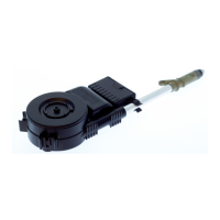
Bei Bedarf kann die Stutzen-
stellung beliebig gewählt
werden.
Dazu die Torx-Schraube
lösen, das Schutzrohr
gemäß der gewünschten
Stellung des Antennen-
kopfes drehen und an-
schließend wieder anziehen.
Indien nodig kan de plaats
van het aansluitstuk wille-
keurig gekozen worden.
Daartoe de torxschroef los-
maken, de beschermbuis
conform de gewenste
plaats van de antennekop
draaien en aansluitend
weer aantrekken.
If necessary the position of
the antenna connection
socket can be optionally
selected.
To do so, loosen the torx-
screw, from the portective
tube to the desired position
of the antenna head and
then tighten the screw
again.
En cas de besoin la position
de la rallonge peut être
choisie selon vos besoins.
A cet effet desserrer la vis
torx, faire tourner le tube
protecteur selon la position
désirée de la tête d'antenne
et alors visser à fond.
Prepare the fixing parts en-
closed in a separate plastic
bag.
For holes of Ø 16,5 mm
the two bars at the lower
spherical half should be
broken off.
In this case the car body
inclination is limited to max.
26°.
For a hole of
Ø 20 - 22 mm the two
bars at the lower spherical
half should not be broken
off.
In this case the car body in-
clination can be about 38°.
Fasten the HF connection
cable (
➄
front mounting,
➅
rear mounting) to the
antenna.
Attach the lower parts as
per the drawing.
Insert the antenna from
underneath into the hole.
Please see that the lower
spherical half has full
contact around the hole.
Slide the sealing washer
and the upper sperical half
over the telescopes and
take care that the upper
spherical half coincides
with the lower spherical
half.
Put on the adapting cover
and the hexagonal nut.
Tighten the hexagonal nut
slightly.
For further antenna heads
for small fenders or fender
inclinations up to 68° see
summary page 8.
 Loading...