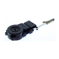
An der Antenne kann der
Halter in verschiedenen
Varianten angebracht wer-
den.
De houder kan op de
antenne in verscheidene
varianten aangebracht wor-
den.
The bracket can be applied
to the antenna in different
positions.
Pour la fixation du support
à l'antenne il y a plusières
variantes.
2. Variante
1. Variante
Die notwendige Halterlänge
und -stellung entsprechend
festlegen.
De noodzakelijke houder-
lengte en -plaats conform
vastleggen.
Determine the length and
the position of the bracket
as required.
Déterminer la longueur et la
position requise du support.
Zur Festlegung der
Teleskopneigung die
Antenne ausfahren:
– Anschlussleitung ein-
stecken.
– Die schwarze Leitung
(sw) an den Minuspol,
dann
– die rote Leitung (rt) an
den Pluspol, dann
– zum Ausfahren die
weiße Leitung (ws) an
den Pluspol der Batterie
anschließen.
Zum Einfahren weiße
Leitung (ws) wieder abneh-
men.
Voor het vastleggen van de
telescoophoek de antenne
naar buiten halen:
– aansluitkabel er insteken.
– de zwarte draad (sw)
aan de minpool, dan
– de rode draad (rt) aan de
pluspool, dan
– voor het naar buiten
halen de witte draad (ws)
aan de pluspool van de
accu aansluiten.
Voor het naar binnen halen
de witte draad (ws) er
weer afhalen.
For setting the telescope
inclination extend the
antenna:
– Plug-in the connection
cable.
– Connect the black cable
(sw) to minus, then
– the red cable (rt) to plus,
finally
– for extending the white
cable (ws) also to plus.
For retracting only dis-
connect the white cable
(ws).
Faire sortir l'antenne afin de
déterminer l'inclinaison du
télescope:
– Enficher les conduites de
raccordement.
– Raccorder la conduite
noire (sw) au pôle négatif,
puis
– la conduite rouge (rt) au
pôle positif et ensuite
– pour sortir l’antenne, rac-
corder la conduite
blanche (ws) au pôle
positif de la batterie.
Pour faire rerentrer,
débrancher la conduite
blanche (ws).
Der obere Knopf am aus-
gefahrenen Teleskop muß
mindestens 100 mm inner-
halb des Fahrzeugumrisses
liegen.
De bovenste knop op de
uitgetrokken telescoop
moet minstens 100 mm
binnen de voertuigomtrek
liggen.
The top of the fully extended
telescope must be at a
distance of 100 mm mini-
mum from the car outline.
Le bouton supérieur du
télescope sorti doit se trou-
ver au moins à 100 mm à
l'intérieur de la silhouette
du véhicule.
 Loading...