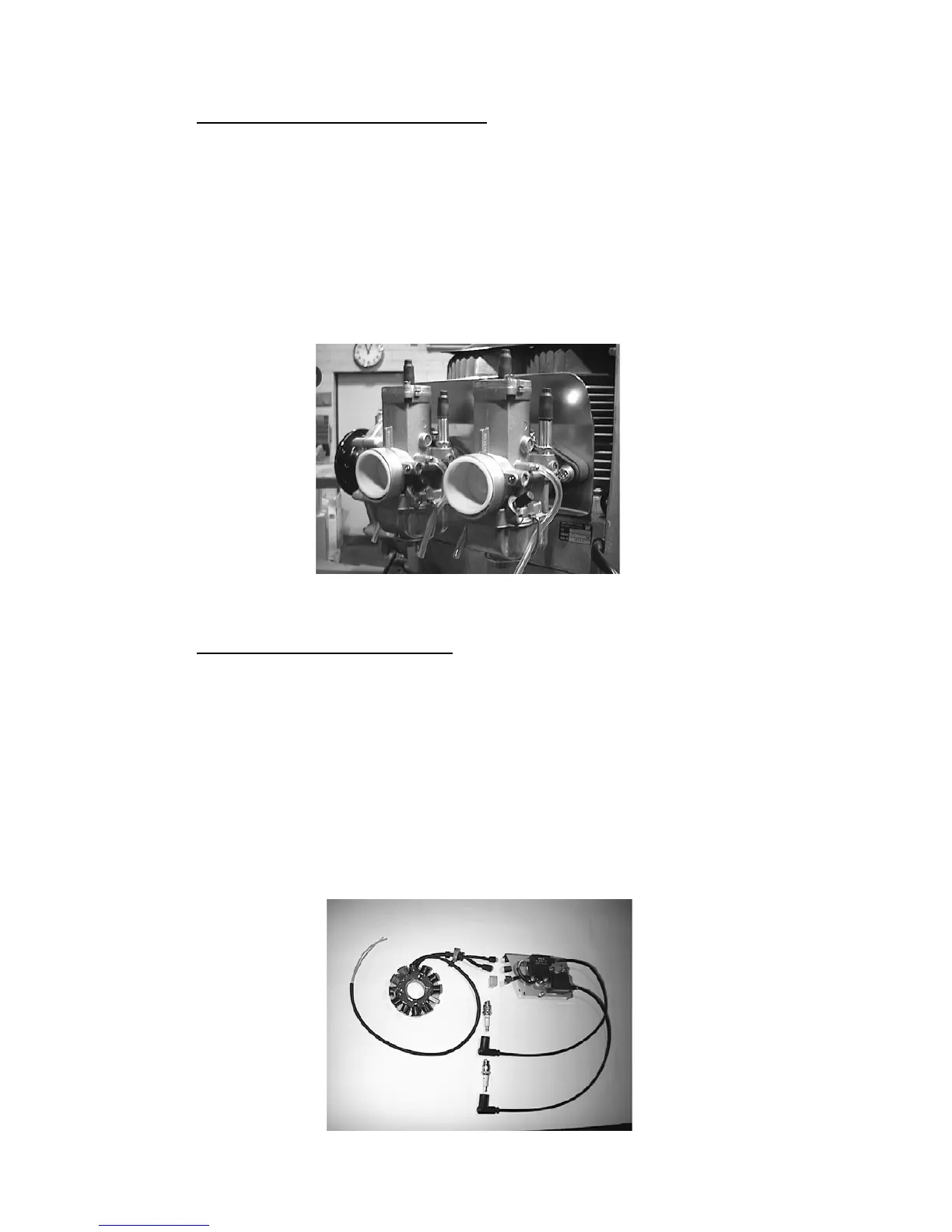
1.1.2 Description of the Carburetion System
The fuel mixture system (Illus. 1.1.2-1) of the 2704 engine consists of one or two carburettors.
Each carburettor is connected to the entry port of the cylinder by an aluminium intake socket
and a rubber flange. The aluminium intake socket is screwed on to the cylinder with cylinder
bolts and lock washers and the carburettor is secured in the rubber flange by a hose clamp.
The carburettor is thermally neutralized by a piece of insulation. The hot cool air stream
exiting from the intake socket is kept apart from the carburettor by shield in the intake socket.
On the intake side of the carburettors are one or two dry air filters.
Illustration 1.1.2-1 (Fuel Mixture [or Carburetion] System)
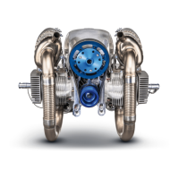
1.1.3 Description of the Ignition System
The ignition system (Illus. 1.1.3-1, 1.1.3-2) consists of an armature plate, a magneto, an E-
Box, two ignition coils and the ignition cables with spark plug caps. The ignition is entirely
electronic and has an e-prom for a free programmable electro-dynamo-magnetic ignition.
There is generator power for electric uses during operation and for charging the battery. The
ignition system is operational with single as well as double ignition. The armature is fastened
to the crankcase on the ignition side. The magneto is situated on the crankshaft and encloses
the armature plate. The fan housing shields the magneto wheel of the ignition. On the fan
housing is the E-Box and the ignition coils on an ignition coil fastener.
Illustration 1.1.3-1 (Single Ignition)