EasyManua.ls Logo

Hisense AMW3-24U4SKC User Manual

Hisense AMW3-24U4SKC
175 pages
To Next Page IconTo Next Page
Page #1 background imageLoading...
Page #1 background image
MULTI-SPLIT TYPE AIR CONDITONER
SERVICEMANUAL
V:7.1
INDOOR UNIT:
AMS-07UR4SN
VG/VT/VL/VQ/UP/UL/UQ/NS/ZC/ZA/NT/NK/NM/VM
4
AMS-09UR4SN
VG/VT/VL/VQ/UP/UL/UQ/NS/ZC/ZA/NT/NK/NM/VM
4
AMS-12UR4SN
VG/VT/VL/VQ/UP/UL/UQ/NS/ZC/ZA/NT/NK/NM/VM
4
AMS-07/09/12UR4SG
NK/NM/VT/VQ
4
AMS-09/12UR4SPSC4
AMS-18U4SV(VG/VQ/VL/VT/UP/UL/UQ/NT/NK/NM
4
AMD-09UX4SJD
AMD-12UX4SJD
AMD-18UX4SJD
AMC-12UX4SAA
AMC-18UX4SAA
OUTDOOR UNIT:
Hisense Corporation
AMW2-16U4SGC1
AMW2-16U4SGD1
AMW2-20U4SNC1
AMW2-20U4SZD1
AMW3-20U4SZD1
AMW3-24U4SAD1
AMW4-28U4SAD1
AMW
4
-
36U4SAD1
AMW3-20U4SZD
AMW3-24U4SZD
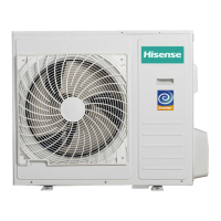
AMW3-24U4SKC
AMW4-28U4SKC
AMW4-36U4SAC
AMV-12UR4SA
AMV-18UR4SA
AS-09/12UR4SVETD5(TG5/TC5/TE5/TF5)
AS-18UR4SFATD5(TD5/TG5/TC5)

Questions and Answers:

Hisense AMW3-24U4SKC Specifications

General IconGeneral
BrandHisense
ModelAMW3-24U4SKC
CategoryAir Conditioner
LanguageEnglish

Summary

1. OPERATING RANGE

2. SPECIFICATIONS

2-1. Unit specifications

Details on the specifications for outdoor and indoor units.

2-1-1. OUTDOOR UNIT

Specific technical specifications for outdoor units.

2-1-2. INDOOR UNIT

Specific technical specifications for indoor units.

2-2. Major component specifications

Specifications for key components like fan motors and compressors.

2-2-1. INDOOR FAN MOTOR

Specifications for indoor fan motors.

2-2-2 OUTDOOR FAN MOTOR

Specifications for outdoor fan motors.

2-2-3. COMPRESSOR

Specifications for the compressor unit.

2-3. Other component specifications

Specifications for other components like inductance, filters, and motors.

2-3-1. INDUCTANCE

Specifications for inductance components.

2-3-2. FILTER

Specifications for filter components.

2-3-4. STEPPER MOTOR

Specifications for stepper motors.

3. OUTLINES AND DIMENSIONS

3-1. INDOOR

Outline and dimensional drawings for indoor units.

3-2. OUTDOOR

Outline and dimensional drawings for outdoor units.

4. REFRIGERANT FLOW DIAGRAM

4-1. Refrigerant flow diagram

Diagram illustrating the refrigerant flow in the system.

4-2 Evacuation procedures

Step-by-step procedures for refrigerant evacuation.

4-3. Evacuation direction

Guidelines for refrigerant pipe length and height difference.

5. ELECTRICAL DATA

5-1.Electrical wiring diagrams

Electrical wiring diagrams for various unit configurations.

5-2. Electric control

Details on electric control systems for indoor and outdoor units.

5-2-1. Indoor control board for indoor unit

Description of the indoor unit control board.

5-2-2. Control board for outdoor unit

Description of outdoor unit control boards.

5-2-3. IPM BOARD

Description of the IPM board.

5-3. Sensor parameter

Parameter data for various temperature sensors.

5-3-1. OUTDOOR COMPRESSOR DISCHARGE TEMPERATURE SENSOR

Parameters for the outdoor compressor discharge temperature sensor.

5-3-2. OTHER SENSOR IN INDOOR AND OUTDOOR UNIT

Parameters for other indoor and outdoor unit sensors.

6. CONTROL MODE

6-1 Indoor control mode

Technical parameters and functions of indoor control mode.

6-2 Outdoor mode control

Performance index and control functions for outdoor mode.

7. TROUBLE SHOOTING

7-1- Error code

Displays and root causes of error codes for indoor and outdoor units.

2. OUTDOOR UNINT FAULT CODE DISPLAY

Indication of faults on the outdoor unit via LEDs.

3. Fault code display ( Driver Board )

Fault code display information for the driver board.

8. CHECKING COMPONENTS

8-1. Check refrigerant system

Procedure for checking the refrigerant system flow.

8-2. Check parts unit

Methods for checking specific unit components.

1. INDOOR FAN MOTOR

Examination and repair of indoor fan motors.

2. OUTDOOR FAN MOTOR

Examination and repair of outdoor fan motors.

3. COMPRESSOR

Examination and repair procedures for the compressor.

4. INDUCTANCE

Checking procedures for inductance components.

5. STEP MOTOR

Checking procedures for step motors.

6. FUSE

Procedure for checking fuse continuity.

7.CAPACITOR

Procedure for checking capacitor health.

9. APPENDIX

For indoor unit

Additional information specific to indoor units.

Related product manuals