Do you have a question about the Hisense AUD-24UX4SZLH and is the answer not in the manual?
Details key features of duct type air conditioners.
Explains power break recovery and self-diagnose functions.
Details key features of cassette type air conditioners.
Details key features of ceiling & floor type air conditioners.
Displays the range of available product types and capacities.
Explains the structure and meaning of model numbers.
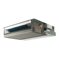
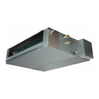
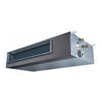
Shows images of duct type indoor and outdoor units.
Shows additional images of duct type indoor and outdoor units.
Shows images of cassette type indoor and outdoor units.
Shows additional images of cassette type indoor and outdoor units.
Shows images of ceiling & floor type indoor and outdoor units.
Explains indicators and controls on the cassette type display panel.
Explains indicators and controls on the ceiling/floor type display panel.
Detailed technical data for duct type air conditioners.
Detailed technical data for cassette type air conditioners.
Detailed technical data for ceiling & floor type air conditioners.
Physical dimensions and diagrams for duct type indoor units.
Additional physical dimensions and diagrams for duct type indoor units.
Physical dimensions and diagrams for 18k cassette type indoor units.
Illustrates installation space requirements for cassette units.
Physical dimensions and diagrams for 24k, 36k, 48k, 60k cassette type indoor units.
Shows mounting and connection details for cassette indoor units.
Physical dimensions and diagrams for ceiling & floor type indoor units.
Physical dimensions and diagrams for 18K outdoor units.
Physical dimensions and diagrams for 18K and 24K outdoor units.
Physical dimensions and diagrams for 24K and 36K outdoor units.
Physical dimensions and diagrams for 48K and 60K outdoor units.
Illustrates refrigerant flow and component connections for different model sizes.
Guidelines and calculations for refrigerant pipe installation limits.
Recommends wire sizes for power and transmitting cables.
Performance charts showing air flow vs. ESP for 18K duct units.
Performance charts showing air flow vs. ESP for 24K duct units.
Performance charts showing air flow vs. ESP for 36K duct units.
Performance charts showing air flow vs. ESP for 48K duct units.
Performance charts showing air flow vs. ESP for 60K duct units.
Cooling capacity curves based on temperature for 18K, 24K, 36K models.
Cooling capacity curves based on temperature for 48K, 60K models.
Electrical wiring diagrams for duct type indoor units.
Electrical wiring diagrams for cassette type indoor units.
Electrical wiring diagrams for ceiling & floor type indoor units.
Electrical wiring diagrams for 18K and 24K outdoor units.
Electrical wiring diagrams for 36K, 48K, and 60K outdoor units.
Details and layout of indoor control boards for duct type units.
Details and layout of indoor control boards for cassette type units.
Details and layout of indoor control boards for ceiling & floor type units.
Details of outdoor control boards for specific models.
Details of outdoor control boards for specific models.
Details of outdoor control boards for specific models.
Details of outdoor control boards for specific models.
Diagrams of IPM boards for various models.
Diagrams of IPM boards for specific models.
Instructions for setting outdoor unit dip switches.
Explanation of the digital display and its operational buttons.
How to adjust static pressure for duct type units.
Guide for adjusting internal system parameters via the controller.
Data table for compressor discharge temperature sensor readings.
Data tables for other temperature sensors.
Details controller functions like emergency switch, timer, sleep, and high power.
Describes outdoor unit protection mechanisms and operation modes.
Explains how fault codes are indicated on various displays and indicators.
How to interpret fault codes from display lamps.
Identifies fault code indicators on cassette unit display panels.
Identifies fault code indicators on ceiling/floor unit display panels.
How fault codes are indicated by outdoor control board lamps.
How fault codes are displayed on digital tubes for outdoor units.
Lists outdoor unit fault codes, causes, and solutions.
Continues the list of outdoor unit fault codes.
Continues the list of outdoor unit fault codes.
Lists outdoor unit fault codes, focusing on expansion valve and sensor issues.
Continues the list of outdoor unit fault codes.
Continues the list of outdoor unit fault codes.
Continues the list of outdoor unit fault codes.
Continues the list of outdoor unit fault codes.
Continues the list of outdoor unit fault codes.
Lists indoor unit fault codes, causes, and solutions.
Continues the list of indoor unit fault codes.
Continues the list of indoor unit fault codes.
Continues the list of indoor unit fault codes.
Lists driver board fault codes, causes, and solutions.
Lists driver board error codes for specific dual types.
Continues the list of driver board error codes.
Procedure for checking the refrigerant system's status.
Testing procedures and resistance values for indoor fan motors.
Testing procedures and resistance values for outdoor fan motors.
Diagrams and testing notes for compressors.
Procedures for testing various electrical components like fuses and capacitors.
| Cooling Capacity | 24000 BTU/h |
|---|---|
| Heating Capacity | 24000 BTU/h |
| Refrigerant | R32 |
| Airflow Rate | 1200 m³/h |
| Power Supply | 220-240V, 50Hz |
| Indoor Unit Noise Level (Low) | 38 dB(A) |
| Outdoor Unit Noise Level | 56 dB(A) |
| Air Flow (Indoor) | 1200 m³/h |
| Type | Split Type |