EasyManua.ls Logo

Hisense AUC-18HR4SSAA1 User Manual

Hisense AUC-18HR4SSAA1
145 pages
To Next Page IconTo Next Page
Page #1 background imageLoading...
Page #1 background image
TECHNICAL & SERVICE MANUAL V1.0
—ON/OFF AIR CONDITIONERS
MODEL:
Duct
AUD-09HX4SVNL
AUD-12HX4SVNL
AUD-18HX4SSNL1
AUD-24HX4SFLH1
AUD-36HX4SDHH2
AUD-36HX6SDHH1
AUD-48HX6SEHH1
AUD-60HX6SPHH1
Cassette
AUC-09HR4SVAA
AUC-12HR4SVAA
AUC-18HR4SSAA1
AUC-24HR4SFGA1
AUC-36HR4SDGA2
AUC-36HR6SDGA1
AUC-48HR6SEHA1
AUC-60HR6SPHA1
Ceiling & Floor
AUV-18HR4SSA1
AUV-24HR4SFA1
AUV-36HR4SDB2
AUV-36HR6SDB1
AUV-48HR6SEC1
AUV-60HR6SPC1
Question and Answer IconNeed help?

Do you have a question about the Hisense AUC-18HR4SSAA1 and is the answer not in the manual?

Hisense AUC-18HR4SSAA1 Specifications

General IconGeneral
BrandHisense
ModelAUC-18HR4SSAA1
CategoryAir Conditioner
LanguageEnglish

Summary

General Information and Product Overview

Product Features

Key features across different unit types like Save Installation Space, Timer, Mute Operation.

Product Lineup and Specifications

Details available models and basic unit construction/working range parameters.

Detailed Product Specifications

Duct Type Specifications

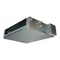
Technical data for Duct models including power, capacity, EER, and coil specs.

Cassette Type Specifications

Technical data for Cassette models including power, capacity, EER, and coil specs.

Ceiling & Floor Type Specifications

Technical data for Ceiling & Floor models including power, capacity, EER, and coil specs.

Unit Dimensions and Electrical Data

Indoor and Outdoor Unit Dimensions

Drawings showing physical dimensions in mm for all indoor and outdoor unit types.

Electrical Specifications

Lists voltage, frequency, and ELB ratings for outdoor units.

Performance Data and Installation Guidelines

Capacity Charts

Tables show cooling and heating capacities at various temperature conditions.

Piping and Sound Data

Correction factors for piping length and sound pressure levels for various units.

Refrigerant Cycle and Wiring Diagrams

Refrigerant Cycle Schematics

Diagrams illustrating refrigerant flow for indoor and outdoor units.

Wiring Diagrams and Control Boards

Electrical diagrams for units and layout of control board components.

Control Modes and Troubleshooting

Control Mode Operations

Explains indoor/outdoor unit control modes, protection features, and timer functions.

Troubleshooting and Error Codes

Guides for identifying and resolving fault codes for indoor and outdoor units.

Component Testing and Checks

Refrigerant System and Fan Motor Testing

Procedures for checking refrigerant system and fan motor resistance.

Compressor and Other Component Testing

Steps for testing compressors, inductance, step motors, fuses, and capacitors.

Related product manuals