3.2 Installation
3.2.1 Suspension bolts
(1) Consider the pipe direction, wiring and maintenance
carefully, and choose the proper direction and location
for installation.
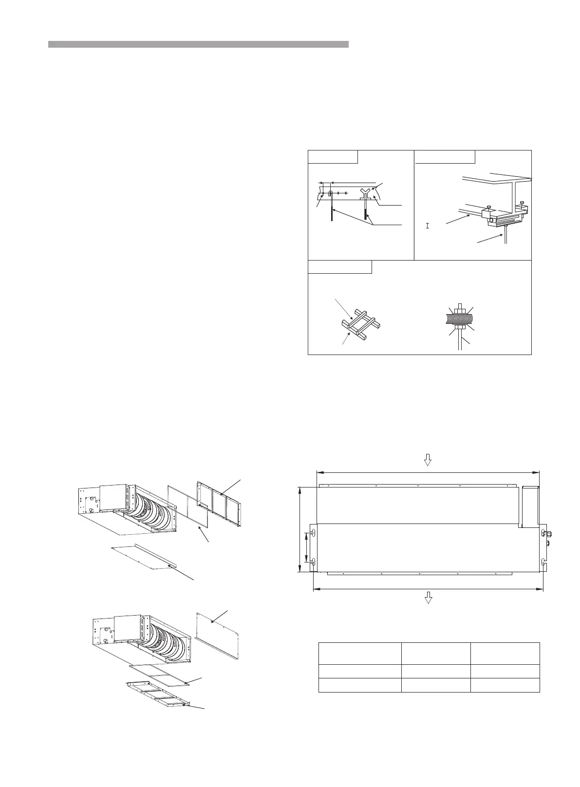
(2) Install the suspension bolts as shown in Fig. 3.2
below.
Fig. 3.2.1 Fixing the suspension bolts
·For the concrete ·For the steel beam
·For the wooden beam
150 to160mm
Screw in
(100 to150kg)
Steel bar
Concrete
Suspension bolts
(W3/8 or M10)
“ ” shaped steel beam
Wood rib
60mm to 90mm ( )
Wooden beam
Nut Round washer
Square washer
Suspension bolts
7
3.2.2 The position of the suspension bolts and the pipes
(1) Mark the positions of the , the
positions of the refrigerant pipes and the drain pipes.
(2) The dimension are shown below.
suspension bolts
Installation and Maintenance
·Optimum air distribution is ensured.
The air passage is not blocked.
Condensate can drain properly.
The ceiling is strong enough to bear the weight of the
indoor unit.
A false ceiling does not seem to be at an incline.
Sufficient clearance for maintenance and servicing
is ensured.(See Fig.3.1.1,Fig3.1.2 )
Piping between the indoor and outdoor units is within
the allowable limits.(refer to the installation of the
outdoor unit )
The indoor unit, outdoor unit, power supply wiring
and transmission wiring is at least 1 meter away from
televisions and radio, this prevents image interference
and noise in electrical appliances.
(Noise may be generated depending on the conditions
under which the electric wave is generated, even if a
one-meter allowance is maintained.)
Use suspension bolts to install the unit, check whether
or not the ceiling is strong enough to support the weight
of the unit. If there is a risk that the ceiling is not strong
enough, reinforce the ceiling before installing the unit.
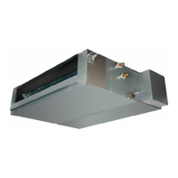
For bottom intake, replace the chamber lid and the
intake-side flange in the procedure listed in fig.
(1)Remove the intake-side flange.
Remove the chamber lid.
(2)Reattach the removed chamber lid in the orientation
shown in FIG, reattach the removed the intake-side
flange in the orientation shown in Fig. 3.1.3, refer to
Fig.3.1.4 for the direction of the intake-side flange.
·
·
·
·
·
·
·
·
·
Do not install the indoor unit in a machinery shop
or kitchen where vapor from oil or its mist flows to
the indoor unit . The oil will deposit on the heat
exchanger, thereby reducing the indoor unit
performance, and may deform and in the worst case,
break the plastic parts of the indoor unit.
Suspension bolts
(W3/8 or M10)
Nut
Fig. 3.1.3
Fig. 3.1.4
Intake-side flange
Chamber lid
Intake-side flange
Chamber lid
Filter(invalid for
Filter(invalid for some models)
some models)
.1
9K/12K/18K
Air inlet
Air outlet
b
154
447
a
 Loading...