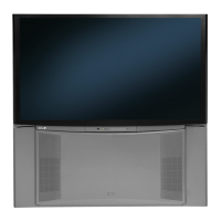
If Position Shifted Crosshatch (as show Figure 2) is displayed, check next items.
1) Check DCU Phase Data
Figure 2
Example Image of Position Shifted DCU Crosshatch
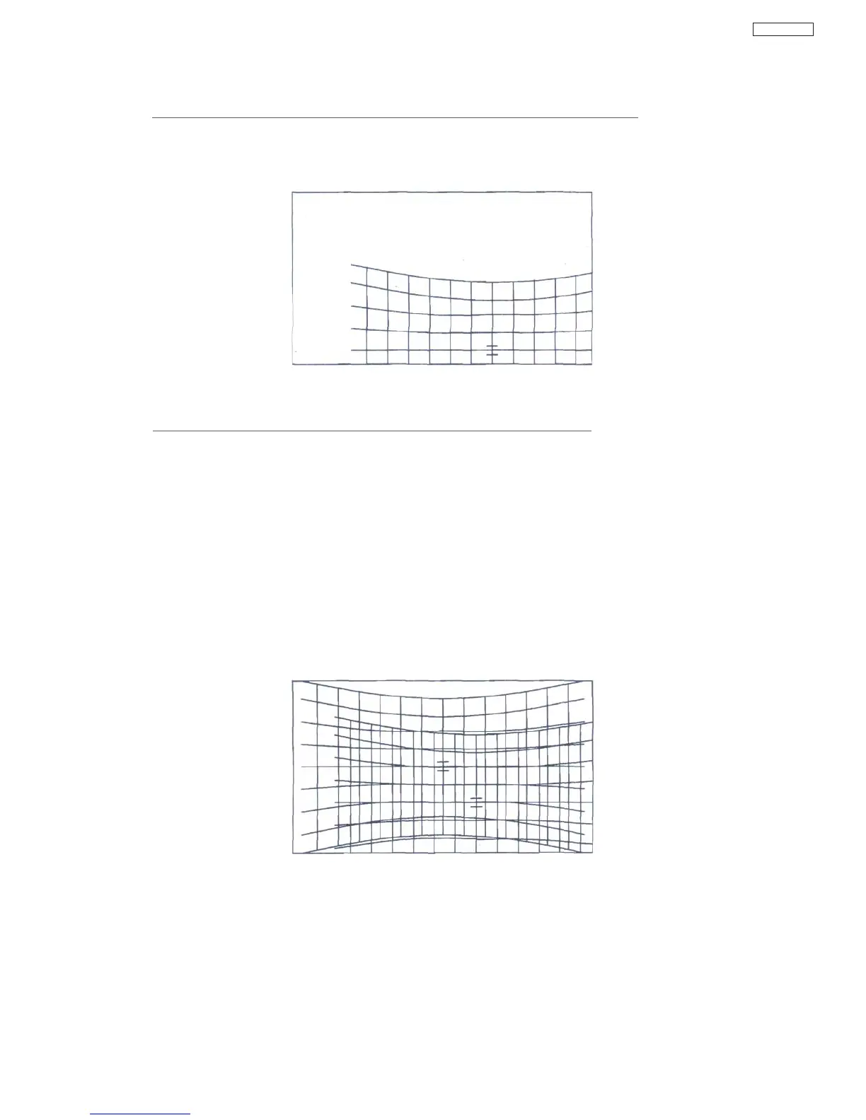
If uneven Crosshatch (as show Figure 3) is displayed, check next items.
1) Assembly Error of DCU uCOM (IS07), EEPROM (IS01, ISOS**
1
), DCU LSI (IS06), DAC
(IT01),
PDT4 connector, or other peripheral parts
2) Solder-Bridge of DCU uCOM (IS07) 1-2,17-24, 27-32, 42-49, 51-55, 75-80pin
3) Solder-Bridge of EEPROM (IS01, IS03
r1
)
4) Solder-Bridge of DCU LSI (IS06) 5, 7, 14, 20-25, 33-35, 38-39, 48-50, 52, 60, 64, 79, 84,
88,
103,110-111,118-125,128-142pin
5) Solder-Bridge of DAC (IT01) 1-5, 8-9, 12-13,16-17, 32-33, 36-37, 40-41, 46~8pin
6) Solder-Bridge of PDT4 connector
7) "H.BLK/V.BLK" signal line (from PDT2 connector 7/11 pin to DCU LSI (IS06) 33/35pin
8) PLL of DCU LSI (RS65/67, CS32)'
9) +5V Power supply line (from PDT3 connector 10/11 pin to DCU LSI (IS06))
10) +3.3V Power supply line (from +3.3V Regulator (IS04) 4pin to DCU LSI (IS06))
Figure 3
Example Image of uneven DCU Crosshatch
Note)
*1 : IS03 (EEPROM) is only use by DP5M chassis.
45
DP65