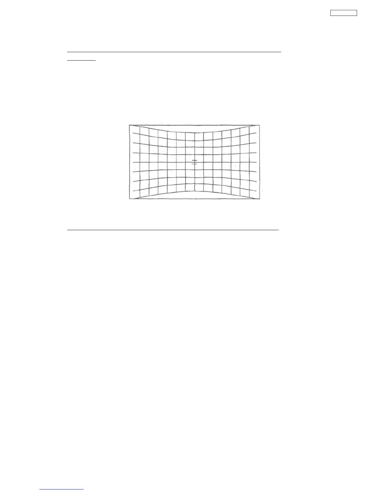
If No Correction Crosshatch (All channels, as show Figure 4) is displayed, check
next items.
1) Assembly Error of Reset 1C (IS05), DCU LSI (IS06), DAC (IT01), or other peripheral parts
2) Solder-Bridge of DCU LSI (IS06) 5, 7,14, 20-25, 27-29, 33-35, 44,52, 88pin
3) Solder-Bridge of DAC (IT01) 4-5, 45pin
4) "Mute" signal line (from QC17-C to DAC (IT01) 45pin)
5) +5V Power supply line (from PDT3 connector 10/11 pin to DAC (IT01))
Figure 4
Example Image of No Correction DCU Crosshatch
If No Correction Crosshatch (Only one or two channels) is displayed, check next items.
1) Assembly Error of DCU LSI (IS06), DAC (IT01), Op-Amp (IT02-07), PDT4 connector, or other
peripheral parts
2) Solder-Bridge of DCU LSI (IS06) 60, 64, 79, 84, 98,103pin
3) Solder-Bridge of DAC (IT01) 1-3, 8-9,12-13,16-17, 32-33, 36~37, 40-41, 46~8pin
4) Solder-Bridge of Op-Amp (IT02~07)
5) Solder-Bridge of PDT4 connector
6) "Correction Data (Digital)" signal line (from DCU LSI (IS06) 60, 64, 79, 84, 98, 103pin to
DAC(IT01) 1-3, 46-48pin)
7) "Correction Data (Analog)" signal line (from DAC (IT01) 8/12/16/33/37/41 pin to PDT4 connector)
8) +5V Power supply line (from PDT3 connector 10/11 pin to Op-Amp (IT02-07))
9) -5V Power supply line (from PDT3 connector 5-6pin to Op-Amp (IT02-07))
46
DP65