HMCS46C,HMCS46CL-------------------------------------------------------
pulse
is
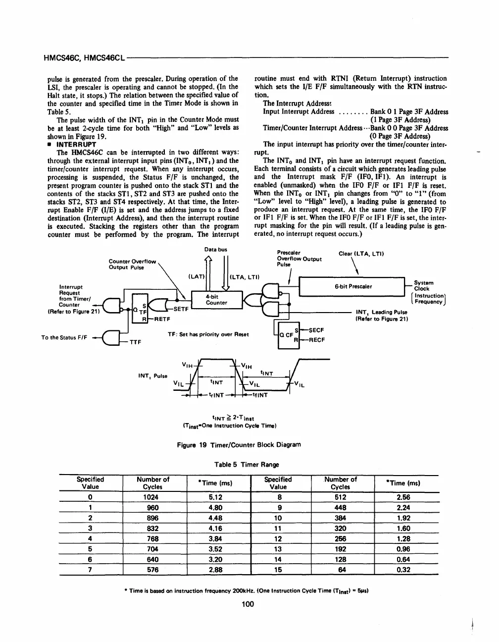
generated from the prescaler. During operation
of
the
LSI,
the prescaler
is
operating and cannot
be
stopped. (In the
Halt state, it stops.) The relation between the specified
value
of
the counter and specified time
in
the Timer
Mode
is
shown in
Table
S.
The
pulse width
of
the
INTI
pin
in
the Counter
Mode
must
be
at least 2-cycle time for both "High" and "Low" levels
as
shown in Figure 19.
• INTERRUPT
The
HMCS46C
can be interrupted in two different ways:
through the external interrupt input pins (INTo, INT
I)
and the
timer/counter interrupt request.
When
any interrupt occurs,
processing
is
suspended, the Status
F/F
is
unchanged, the
present program counter
is
pushed onto the stack STI and the
contents
of
the stacks
STl,
ST2 and
ST3
are
pushed onto the
stacks
ST2,
ST3
and ST4 respectively. At that time, the Inter-
rupt Enable F /F (I/E)
is
set and the address jumps
to
a fixed
destination (Interrupt Address), and then the interrupt routine
is
executed. Stacking the registers other than the program
counter must
be
performed by the program. The interrupt
Interrupt
Request
from Timer/
Counter
(Refer
to
Figure 21)
To the
Status F/F
Data bus
TF:
Set has priority over Reset
INT, Pulse
routine must end with RTNI (Return Interrupt) instruction
which sets the I/E F
/F
simultaneously with the RTN instruc-
tion.
The Interrupt
Address~
Input Interrupt Address
........
Bank 0 1
Page
3F
Address
(1
Page
3F
Address)
Timer/Counter Interrupt Address··· Bank 0 0
Page
3F Address
(0
Page
3F
Address)
The input interrupt has priority over the timer/counter inter-
rupt.
The
INTo
and INTI pin
have
an interrupt request function.
Each terminal consists
of
a circuit which generates leading pulse
and the Interrupt mask F/F
(IFO,
IFI).
An
interrupt
is
enabled (unmasked) when the
IFO
F/F
or IFI F/F
is
reset.
When
the
INTo
or INTI pin changes from
"0"
to
"I"
(from
"Low" level to "High" level), a leading pulse
is
generated to
produce an interrupt request. At the
same
time, the
IFO
F/F
or IFI F/F
is
set.
When
the
IFO
F/F
or IFI
F/F
is
set, the inter-
rupt masking for the pin
will
result.
(If
a leading pulse
is
gen-
erated, no interrupt request occurs.)
Prescaler
Overflow
Output
Pulse
I
SECF
RECF
6·bit Prescaler
INT,
Leading Pulse
(Refer
to
Figure 21)
System
Clock
(
InstructionJ
Frequency
tiNT
~
2·Tinlt
(Tinst-One Instruction Cycle Time)
Figure
19
Timer/Counter Block Diagram
Table 5 Timer
Range
Specified
Number
of
*Time
(ms)
Specified
Number
of
*Time
(ms)
Value
Cycles Value Cycles
0 1024
5.12 B
512
2.56
1
960
4.80
9 448 2.24
2
896
4.48
10
384
1.92
3
832
4.16
11
320 1.60
4
768 3.84 12 256 1.28
5
704 3.52 13 192
0.96
6 640
3.20
14
128
0.64
7 576
2.88
15
64
0.32
• Time
is
based on instruction frequency 200kHz. (One Instruction Cycle Time (Tlnst) ..
5$ls)
100
 Loading...

