------------------------------------------------------HMCS46C,HMCS46CL
LSI
Intemel
Clock
I r
tl>1
ltl>2
SED.
RED.[
SEDD.
REDO
Instruction
TO
[
Instruc·
tion
/
o ne nstructlon
C I
yce\
M
i"""""""1
-
r----l
r-----l
-
On
Set/Reset
Instruction
On
(LSI pin)
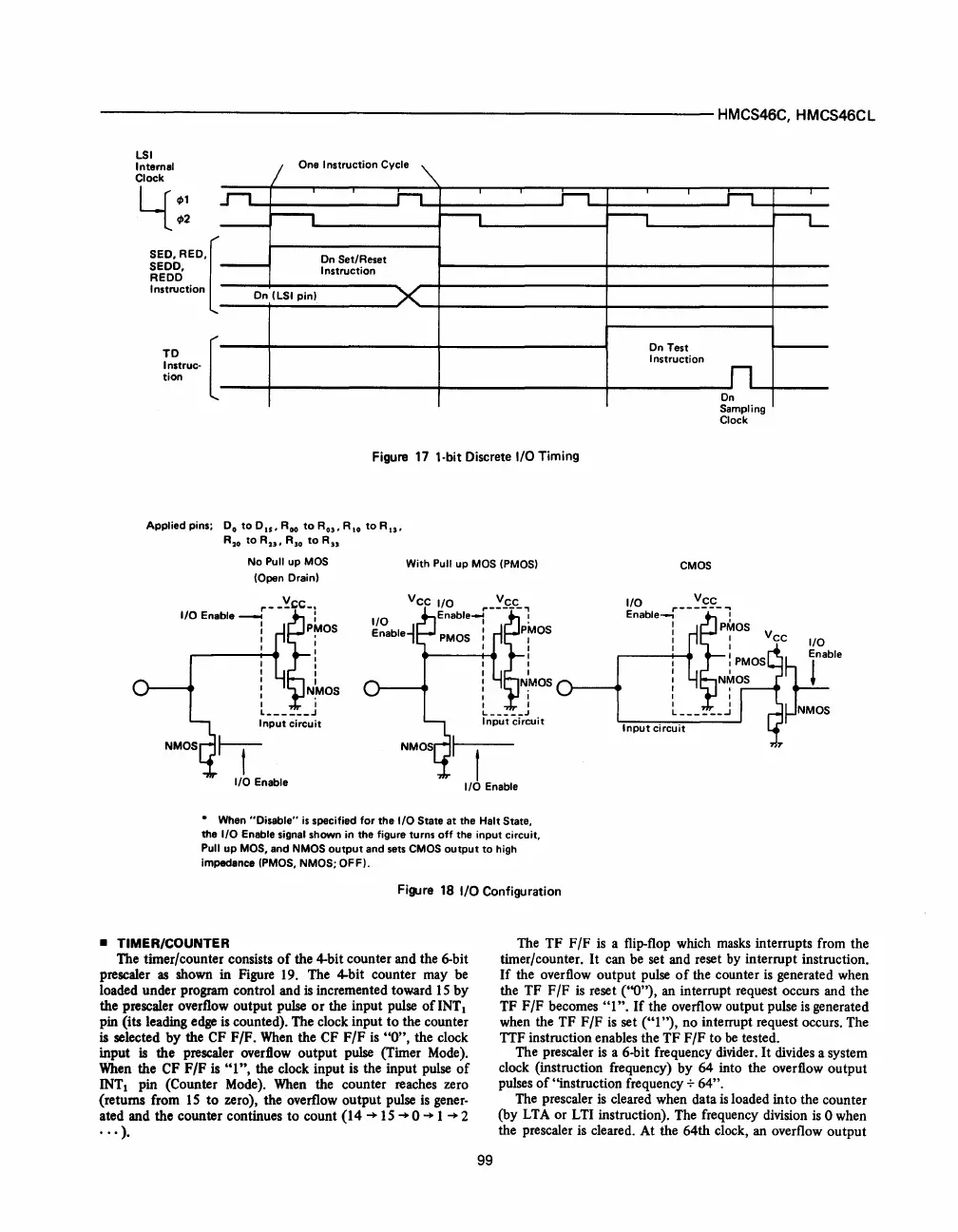
Figure
17
1·bit Discrete
I/O
Timing
Applied pins;
Do
to
0
15
,
Roo
to
R
03
'
R,O
to
Ru.
R
20
to
Ru.
R30
to
Ru
No
Pull up
MOS
(Open Drain)
I/O Enable
~-
-'!.~CC-l
: PMOS
,..------t:......
:
I :
I I
I I
:
N,MOS
I I
L
______
J
Input circuit
~
I/O Enable
With Pull
up
MOS
(PMOS)
Vee I/O
vee
I/O
Enable--f---~--1
E
bl
J I PMOS
na
e1
PMOS
I I
I I
.....
----t-.. I
I I
I I
I
NMOS
I .
I I
I I
L
_____
.I
Input circuit
t
I/O Enable
•
When "Disable"
is
specified for
the
I/O
State
at
the Halt State.
the
I/O Enable signal shown in the figure turns
off
the input circuit.
Pull
up
MOS.
and
NMOS
output
and
sets
CMOS
output
to
high
impedance
(PMOS. NMOS; OFF),
Figure 18
I/O
Configuration
r--t
On
Test
Instruction
CMOS
h
On
Sampling
Clock
r---L-
I I ee
~~blei--~~~s:-plos
V
I/O
I I
r-------t-~
:
PMOS
NMOS
I
I
I I
L
______
.J
Input
circuit
~ble
~NMOS
• TIMER/COUNTER The
TF
F
/F
is a flip-flop which masks interrupts from the
timer/counter. It can be set and reset by interrupt instruction.
If
the overflow
output
pulse
of
the counter is generated when
the
TF
F
IF
is reset (''0''), an interrupt request occurs and the
TF
F/F
becomes
"1".
If
the overflow output pulse is generated
when the
TF
F
IF
is set
("I
"),
no interrupt request occurs. The
TTF instruction enables the
TF
F/F
to
be
tested.
The timer/counter consists
of
the 4-bit counter and the 6-bit
pre scaler
as
shown in Figure 19. The 4-bit counter may be
loaded under program control and
is incremented toward 15
by
the prescaler overflow output pulse
or
the input pulse
of
INT 1
pin (its leading edge is counted). The clock input
to
the counter
is selected
by
the CF
F/F.
When the CF
F/F
is
"0",
the clock
input
is
the
prescaler overflow
output
pulse (Timer Mode).
When the
CF
F/F
is
"1",
the clock input is the input pulse
of
INTI pin (Counter Mode). When the counter reaches zero
(returns from
15
to
zero), the overflow output pulse is gener-
ated and the counter continues
to
count
(14
-+
15 -+ 0
-+
1
-+
2
...
).
99
The prescaler is a 6-bit frequency divider.
It
divides a system
clock (instruction frequency)
by
64 into the overflow
output
pulses
of
"instruction frequency
-:-
64".
The prescaler is cleared when data
is
loaded into the counter
(by LTA
or
LTI instruction). The frequency division is 0 when
the prescaler is cleared. At the 64th clock, an overflow
output
 Loading...

