-------------------------------------------------------HMCS47C,HMCS47CL
CAUTION
up
MOS.
These currents are added to
the Stand-by Supply
Current (or Halt
Current).
If, during the Halt State, the external reset input
is
applied
(RESET
=
"I"
("High"level)), the internal status is not held.
"Disable"1output
.......
NMOS
Output: OFF
CMOS
Output:
High Impedance
(NMOS,
PMOS:
OFF)
Pull up
MOS
...
OFF
Input
.........
Input Circuit:
OFF
• OSCILLATOR
The
HMCS47C
contains its own oscillator and frequency
divider
(CPG). The user can obtain the desired timing for opera-
tion
of
the LSI
by
merely connecting
an
resistor
Rf
or ceramic
filter circuit (Internal
Clock Operation). Also an external
oscil-
lator can supply a clock (External Clock Operation).
Both input and output
are
at high
impedance state.
Since an input circuit
The
OSC
I
clock frequency
is
internally divided by four
to
produce the internal system clocks.
is
OFF, any current other than the Stand-
by Supply Current (or Halt Current) does
__
not
flow even
if
an input signal changes.
When the HLT pin is set
to
"I"
("High" level), the
HMCS47C
gets into operation from the status just before the Halt State.
The user may exchange the external parts for the same
LSI
to
select either
of
these two operational modes
as
shown in
Figure 25. There
is
no need
of
specifying
it
by using the mask
option.
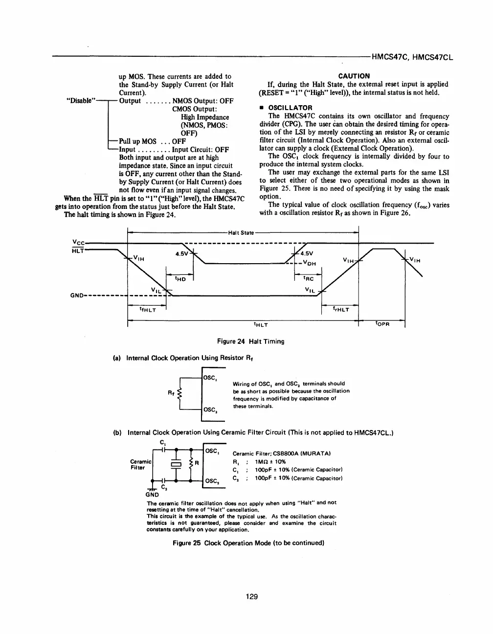
The halt timing
is shown in Figure 24.
The typical value
of
clock oscillation frequency (fose) varies
with a oscillation reSistor Rf
as
shown
in
Figure 26.
t--------------HaltState------------~
vcc----------+-------
____
~
HlT----.
GND---------
tfHLT
frHLT
tOPR
Figure 24 Halt Timing
(a)
Internal Clock Operation Using Resistor R
t
c{
SC,
Wiring of asc,
and
asc, terminals should
Rt
be as
short
as
possible because
the
oscillation
frequency
is
modified by capacitance of
asc, these terminals.
(b) Internal Clock Operation Using Ceramic Filter Circuit (This
is
not
applied
to
HMCS47CL.)
c,
~~~:~iCrt--
......
_
......
~
}C
2
Ceramic Filter; CSB800A (MURATA)
R,
1MO ± 10%
C,
100pF
± 10% (Ceramic Capacitor)
C
2
100pF
± 10% (Ceramic Capacitor)
GND
The
ceramic filter oscillation does
not
apply when using
"Halt"
and
not
resetting
at
the
time of
"Halt"
cancellation.
This circuit
is
the
example of
the
typical use.
As
the
oscillation charac·
teristics
is
not
guaranteed, please consider and examine
the
circuit
constants
carefully
on
your
application.
Figure 25 Clock Operation Mode
(to
be continued)
129
 Loading...

