LCD-III---------------------------------
Refer to
LIQUID
CRYSTAL
DISPLAY
for additional
in-
formation.
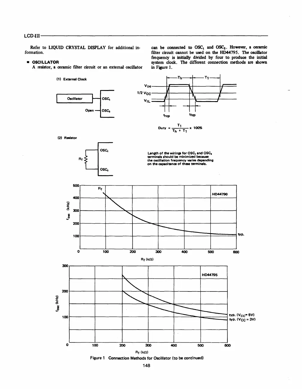
• OSCILLATOR
A resistor, a ceramic filter circuit or an external oscillator
can be connected to
OSC
1
and
O~.
However, a ceramic
filter circuit cannot
be
used on the HD44795. The oscillator
frequency
is initially divided by four
to
produce the initial
system clock. The different connection methods
are
shown
in
Figure
1.
(1) External Clock
Oscillator
(2) Resistor
VIH----h,::::===\...~---_I_I===
1/2
VCC------j~---+..l!r____----+_-
VIL
:::::;:jtj--i4:::::::::::::::t---
trcp
tfcp
tt
SC1
Rf
OS(1
Length
of
the
wirings for
OSc.
and
OS(1
terminals should be minimized because
the
oscillation frequency veries depending
on
the
capacitance
of
these terminals.
500
400
N
:r
~
300
II
~
200
100
0
300
200
N
:r
~
j
100
o
Rf
"
100
100
HD44190
~
"
~
-
-----
I----
typo
200
300
400
500
600
Rf
(kn)
~
HD44795
~
~'
~
~
~
r------
tYPo
(Vee·
5V)
typo (VCC = 3V)
200
300
Rf(kn)
400
-
500 600
Figure 1 Connection Methods
for
Oscillator
(to
be continued)
148