----------------------------------
LCD-III
• Counter Mode
Counts pulses
of
INT
1 terminal.
(Note) The width
of
INTl pulse
in
the counter mode must
be
at least 2-cycle time for both the "High" and
"Low"
levels.
Each block
of
timer/counter and the specified time
of
timer
mode
are
explained in the followings.
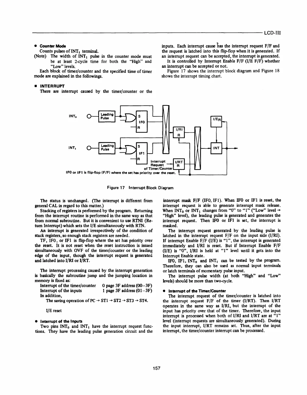
• INTERRUPT
There
are
interrupt caused by the timer/counter or the
inputs. Each interrupt
cause
has the interrupt request F
/F
and
the request
is
latched into this flip-flop when it
is
generated.
If
an interrupt request can be accepted, the interrupt
is
generated.
It
is
controlled by Interrupt
Enable
F/F (I/E F/F) whether
an
intefl1lpt can be accepted or not.
Figure
17
shows
the interrupt block diagram and Figure
18
shows
the interrupt timing chart.
Figure 17
Interrupt
Block
Diagram
The status
is
unchanged. (The interrupt
is
different from
general
CAL
in regard
to
this matter.)
Stacking
of
registers
is
performed by the program. Returning
from the interrupt routine
is
performed in the
same
way
as
that
from normal subroutine. But it
is
convenient
to
use
RTNI (Re-
turn Interrupt) which sets the I/E simultaneously with
RTN.
An
interrupt is generated irrespectively
of
the condition
of
stack registers,
so
enough stack registers
are
needed.
TF,
IFO, or 1Ft
is
flip-flop where the set has priority over
the reset. It
is
not reset when the reset instruction
is
issued
simultaneously with
OVF
of
the timer/ counter
or
the leading
edge
of
the input, though the interrupt request
is
generated
and latched into I/RI or I/RT.
The interrupt processing caused by the interrupt generation
is
basically the subroutine jump and the jumping location in
memory
is
flXed
as:
Interrupt
of
the timer/counter 0
page
3F address (OO-3F)
Interrupt
of
the inputs 1
page
3F address
(01-3F)
In addition,
The
saving
operation
of
PC
~
STl
~
ST2
~
ST3
~
ST4.
I/E reset
• I
nterrupt
of
the
Inputs
Two pins
INTo
and INT 1
have
the interrupt request func-
tions. They
have
the leading pulse generation circuit and the
157
interrupt mask F/F (IFO,IF1).
When
IFO
or 1Ft is reset, the
interrupt request
is
able to generate interrupt mask release.
When
INTo
or INT 1 changes from
"0"
to
"t"
("Low"
level
~
"High" level), the leading
pulse
is
generated and generates the
interrupt request. Then
IFO
or 1Ft
is
set, the interrupt
is
masked.
The interrupt request generated by the leading pulse
is
latched in the interrupt request F/F on the input
side
(I/RI).
If
interrupt Enable F
/F
(I/E)
is
"1",
the interrupt
is
generated
immediately and I/RI
is
reset. But if Interrupt Enable F
/F
(I/E)
is
"0",
I/RI
is
held at
"1"
level
until it gets into the
Interrupt Enable state.
IFO,
1Ft,
INTo
and INTi can be tested by the program.
Therefore, they
can
also
be
used
as
normal input terminals
or latch terminals
of
momentary
pulse
input.
The interrupt
pulse
width (at both "High" and "Low"
levels) should
be
more
than
two-cycle.
•
Interrupt
of
the
Timer/Counter
The interrupt request
of
the timer/counter
is
latched into
the interrupt request F/F
of
the timer (I/RT). Then I/RT
operates
in
the
same
way
as
I/RI, but the interrupt
of
the
input
has
priority over that
of
the timer. Therefore, the input
interrupt
is
processed when both
of
I/RI and I/RT
are
at
"1"
level
(interrupt requests
are
simultaneously generated). During
the input interrupt, I/RT remains set. Thus, after the input
interrupt, the timer/counter interrupt can be processed.
 Loading...

