LCO-III--------------------------------
• TIMER/COUNTER
Dilcrete 1/0
output Iitch
:-----,
• 0 "--.....<fI
,
___
I:_J-
Dilcrete
110
output Iitch
,-----,
r--------~:
Oil
i-:
--+-
.......
O'~~J-4.......-_~
!:!:c~~I~:::~.tch
L - - - -
~
..
tlip!,)
5-bit divider
32.768kHz
Cryltal
circuit
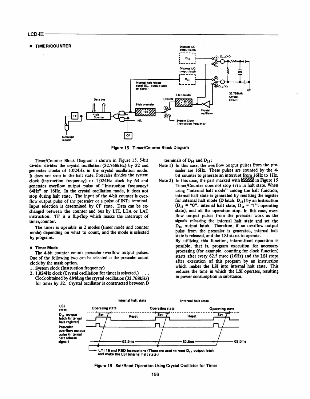
Figure 15 Timer/Counter Block Diagram
Timer/Counter Block Diagram
is
shown
in
Figure 15. 5-bit
divider divides the crystal oscillation (32.768kHz) by 32 and
generates clocks
of
1.024Hz
in
the crystal oscillation mode.
It does not stop
in
the halt state. Prescaler divides the system
clock (instruction frequency)
or
I,024Hz clock by 64 and
generates overflow output pulse
of
"Instruction frequency /
64Hz"
or
16Hz. In the crystal oscillation mode, it does not
stop during halt state. The input
of
the 4-bit counter is over-
flow
output pulse
of
the prescaler or a pulse
of
INTI terminal.
Input selection
is determined by CF state. Data can be ex-
changed between the counter and bus by L TI, LT A
or
LAT
instruction. TF
is
a flip-flop which masks the interrupt
of
timer/counter.
The
timer
is
operable in 2 modes (timer mode and counter
mode) depending on what to count, and the mode
is
selected
by programs.
• Timer
Mode
The
4-bit counter counts prescaler overflow output pulses.
One
of the following two can
be
selected
as
the prescaler count
clock by the mask option.
1. System clock (Instruction frequency)
2.
"1
,024Hz clock (Crystal oscillation for timer
is
selected.)
Clock obtained by dividing the crystal oscillation (32.768kHz)
for timer by 32.
Crystal oscillator
is
constructed between 0
hitifflil
hilt
itiii
terminals
of
0
14
and
015
:
Note 1)
In
this case, the overflow output pulses from the pre-
scaler
are
16Hz. These pulses
are
counted by the
4-
bit counter
to
generate an interrupt from 16Hz to 1Hz.
Note 2)
In
this case, the part marked with
~
in Figure
15
Timer/Counter does not stop
even
in
halt state.
When
using "internal halt mode" among the halt function,
internal halt state
is
generated by resetting the register
for internal halt mode
(0
latch: 0
15
)
by
an instruction
(D15
= ''0''; internal halt state, 0
15
=
"1";
operating
state), and
all
the operation stop.
In
this case, over-
flow
output pulses from the prescaler work
as
the
signals
releaSing
the internal halt state and set the
015
output latch. Therefore,
if
an overflow output
pulse from the prescaler
is
generated, internal halt
state
is
released, and the LSI starts
to
operate.
By
utilizing this function, intermittent operation
is
possible, that is, program execution for necessary
processing (for example, counting for clock function)
starts after every 62.5 msec (16Hz) and the
LSI
stops
after execution
of
this program by
an
instruction
which makes the
LSI
into internal halt state. This
reduces the time in which the
LSI
operates, resulting
in
power consumption in substance.
i nternei neit Itete
LSI
Operetlng
.tete
Operating
.tete
Operetlng stete
.tete
Ou
output
letch (internel
helt regl.ter)
Presceler
overflow
output
pulse (lnternel
helt
reln.e
.Ignel)
-
--
---
--~e~;t-
- - -
--
- Set
---
-
--
--R~;t--
- - - -
-~--
---
-~----
62.5m.----+-+-----62.5m.---....j..4---
62.5m.
L
YI
15 end
RED
In.tructlons (These ere used to reset
Ou
output letch
end
make the
LSI'
Internel helt .tete.)
Figure 16 Set/Reset Operation
Using
Crystal Oscillator
for
Timer
156
 Loading...

