----------------------------------
LCD-III
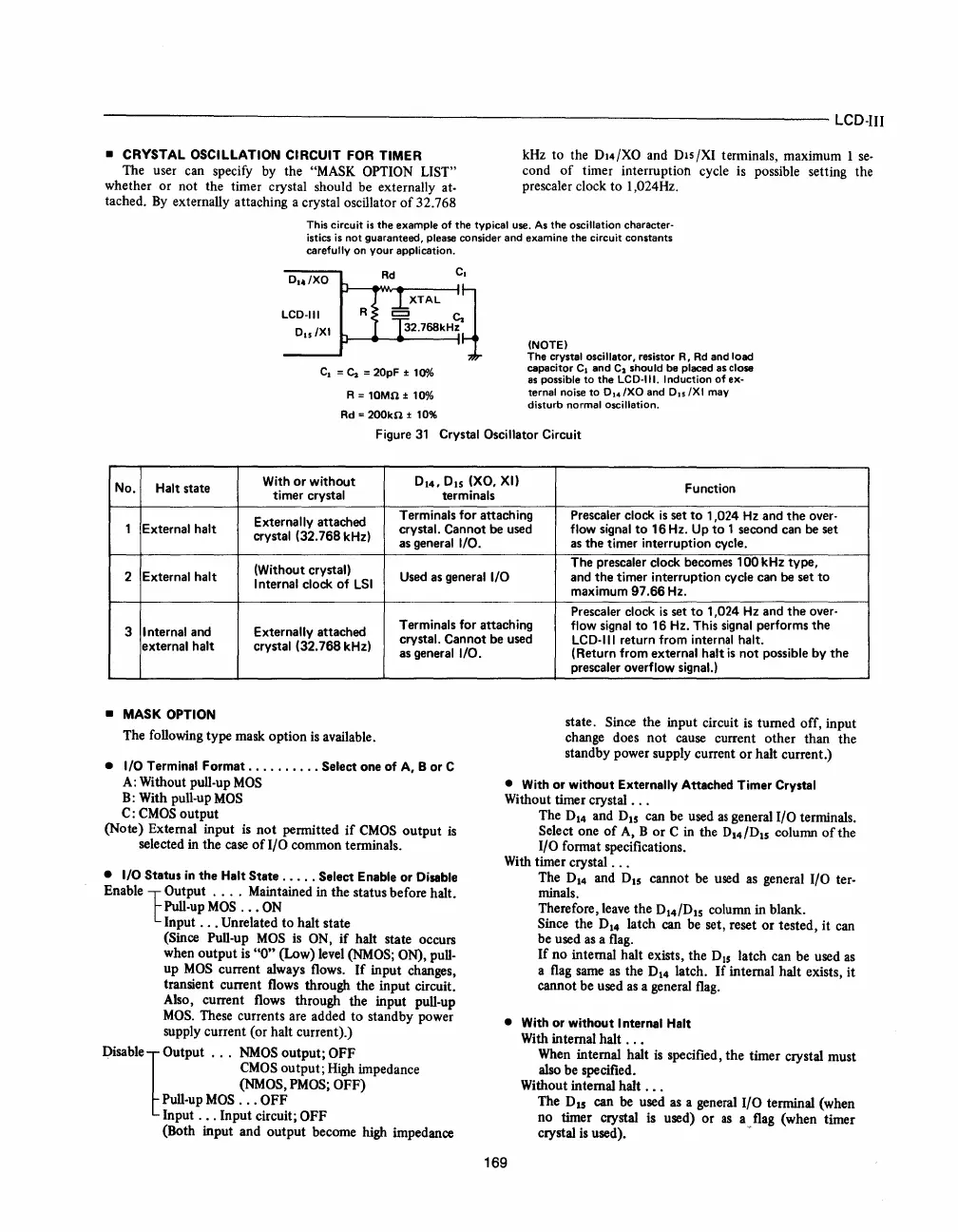
• CRYSTAL OSCILLATION CIRCUIT FOR TIMER
The user can specify
by
the "MASK OPTION LIST"
whether or not the timer crystal should be externally at-
tached.
By
externally attaching a crystal oscillator
of
32.768
kHz to the
DI4/XO and Dis/XI terminals, maximum 1
se-
cond
of
timer interruption cycle
is
possible setting the
prescaler clock to 1,024Hz.
This circuit
is
the
example
of
the
typical use.
As
the
oscillation character-
istics
is
not guaranteed, please consider and examine
the
circuit constants
carefully on your application.
D1./XO
LCD-III
Du/
XI
R
C
1
=
~
= 20pF ±
10"A>
R = 10Ml1 ±
10%
Rd =
200kl1
±
10%
(NOTE)
The
crystal oscillator, resistor R,
Rd
and load
capacitor C
1
and
C
2
should be placed as close
as
possible
to
the
LCD·III. Induction
of
ex-
ternal
noise
to
D,./XO
and
0"
/XI may
disturb
normal oscillation.
Figure
31
Crystal Oscillator Circuit
No. Halt state
With
or
without
0
1
4,
DIS
(XO, XI)
timer crystal
terminals
Externally attached
Terminals for attaching
1 External halt crystal. Cannot be used
crystal (32.768 kHz)
as general
I/O.
(Without crystal)
2
External halt Used
as
general I/O
I
nternal clock
of
LSI
3
I nternal and Externally attached
Terminals for attaching
crystal. Cannot be used
external halt crystal (32.768 kHz)
as general
I/O.
•
MASK
OPTION
The following type mask option
is
available.
• I/O Terminal Format
..........
Select one of A, B or C
Function
Prescaler clock
is
set
to
1,024
Hz
and
the
over-
flow signal
to
16 Hz. Up
to
1 second can be set
as
the
timer interruption cycle.
The prescaler clock becomes
100kHz
type,
and
the
timer interruption cycle can be set
to
maximum
97.66
Hz.
Prescaler clock
is
set
to
1,024
Hz
and
the
over-
flow signal
to
16 Hz. This signal performs
the
LCD-III return from internal halt.
(Return from external halt
is
not
possible by
the
prescaler overflow
signaL)
state. Since the input circuit
is
turned off, input
change does
not
cause current other than the
standby power supply current
or
halt current.)
A:
Without pull-up
MOS
B:
With pull-upMOS
• With or without Externally Attached Timer Crystal
Without timer crystal
...
C:
CMOS
output
(Note) External input
is
not
pennitted
if
CMOS
output
is
selected in the
case
of
I/O common tenninals.
• I/O Status
in
the
Halt State
.....
Select Enable or Disable
Enable
10utput
. . . . Maintained in the status before halt.
Pull-up
MOS
...
ON
Input
...
Unrelated to halt state
(Since Pull-up
MOS
is
ON,
if
halt state occurs
when output
is
"0"
(Low) level
(NMOS;
ON), pull-
up
MOS
current always flows.
If
input changes,
transient current flows through the input circuit.
Also, current flows through the input pull-up
MOS.
These currents are added to standby power
supply current (or halt current).)
Disable
1 Output
NMOS
output; OFF
CMOS
output;
High
impedance
(NMOS,
PMOS;
OFF)
Pull-up
MOS
...
OFF
Input
...
Input circuit; OFF
(Both input and output become high impedance
The
D14
and D
15
can be used
as
general I/O tenninals.
Select one
of
A,
B
or
C
in
the D
14
/D
15
column
of
the
I/O fonnat specifications.
With timer crystal
...
The
D14
and
DIS
cannot
be
used
as
general I/O ter-
minals.
Therefore, leave the D
14
/D
15
column in blank.
Since the
D14
latch can be set, reset
or
tested, it can
be used
as
a
flag.
If
no internal halt exists, the D
I5
latch can be used
as
a
flag
same
as
the
D14
latch.
If
internal halt exists, it
cannot be used
as
a general
flag.
• With
or
without I nternal Halt
With internal halt
...
169
When
internal halt
is
specified, the timer crystal must
also be specified.
Without internal halt
...
The D
15
can be used
as
a general I/O terminal (when
no timer crystal
is
used) or
as
a flag (when timer
crystal
is
used). -
 Loading...

