------------------------------------------------------------------LCD-IV
8. Applied
to
external
clock
operation (system
clockl.
Open
OSC
2
9. Applied
to
internal
clock
operation using resistor
Rt.
(system
clockl
TI
Duty
=
---
x 100%
Th +
TI
Wiring
of
OSC
I
and OSC
2
terminals should
be
as
short
as
possible
because
the oscillation frequency
is
modified
by
capaci-
tance
of
these terminals.
10. Applied
to
internal
clock
operation using ceramic
filter.
(system
clockl
11. Power supply
condition
Vee
~
VI
~ V
2
~ Va ~
GND
should
be
maintained.
__
.
12.
Applied
to
input
pins,
I/O
common
pins among 0 and R terminals, and RESET,
HLT,
ose,
,
INTo,
INT,
pans.
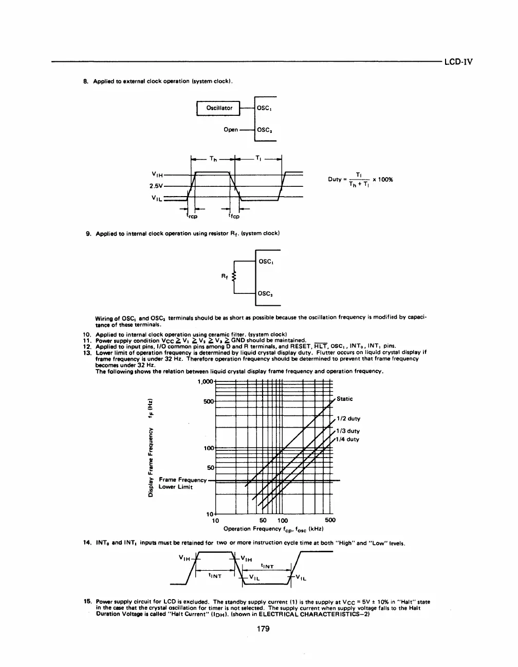
13. Lower
limit
of
operation frequency
is
determined
by
liquid
crystal display
duty.
Flutter
occurs on
liquid
crystal display
if
frame frequency
is
under
32
Hz. Therefore operation frequency should
be
determined
to
prevent
that
frame frequency
becomes under
32
Hz.
The
following
shows the relation between
liquid
crystal display frame frequency and operation frequency.
1,000
500
~
f
u..
i;' Frame Frequency
~
Lower
Limit
i5
00
50
1
0
10
/
./
./
./
/
//
;
V'
V
"'I/~
50
100
/
/
./
Vv
/
S
tatic
V
'
V
'
12
duty
/3
duty
4
duty
V
'
/
500
Operation Frequency f
cp
, f
olc
(kHzl
14. INTo and
INTI
inputs
must
be
retained
for
two
or
more instruction cycle
time
at
both
"High"
and
"Low"
levels.
15. Power supply
circuit
for
LCD
is
excluded. The standby supply current
(11
is
the supply
at
Vee
=
5V
± 10%
in
"Halt"
state
in the
case
that
the crystal oscillation
for
timer
is
not
selected. The supply current when supply voltage falls to the
Halt
Duration Voltage
is
called
"Halt
Current"
(lOHI.
(shown in
ELECTRICAL
CHARACTERISTlCS-21
179



 To Next Page