---------------------------------
LCD-IV
• PATTERN GENERATION
The pattern (constant) can
be
accessed by the pattern instruc-
tion (P). The pattern can be written in any address
of
the
ROM
address space.
• Reference
ROM
addressing for reference
of
the patterns
is
achieved by
modifying the program counter with the accumulator, the B
register, the
Carry F/F and the operand
p.
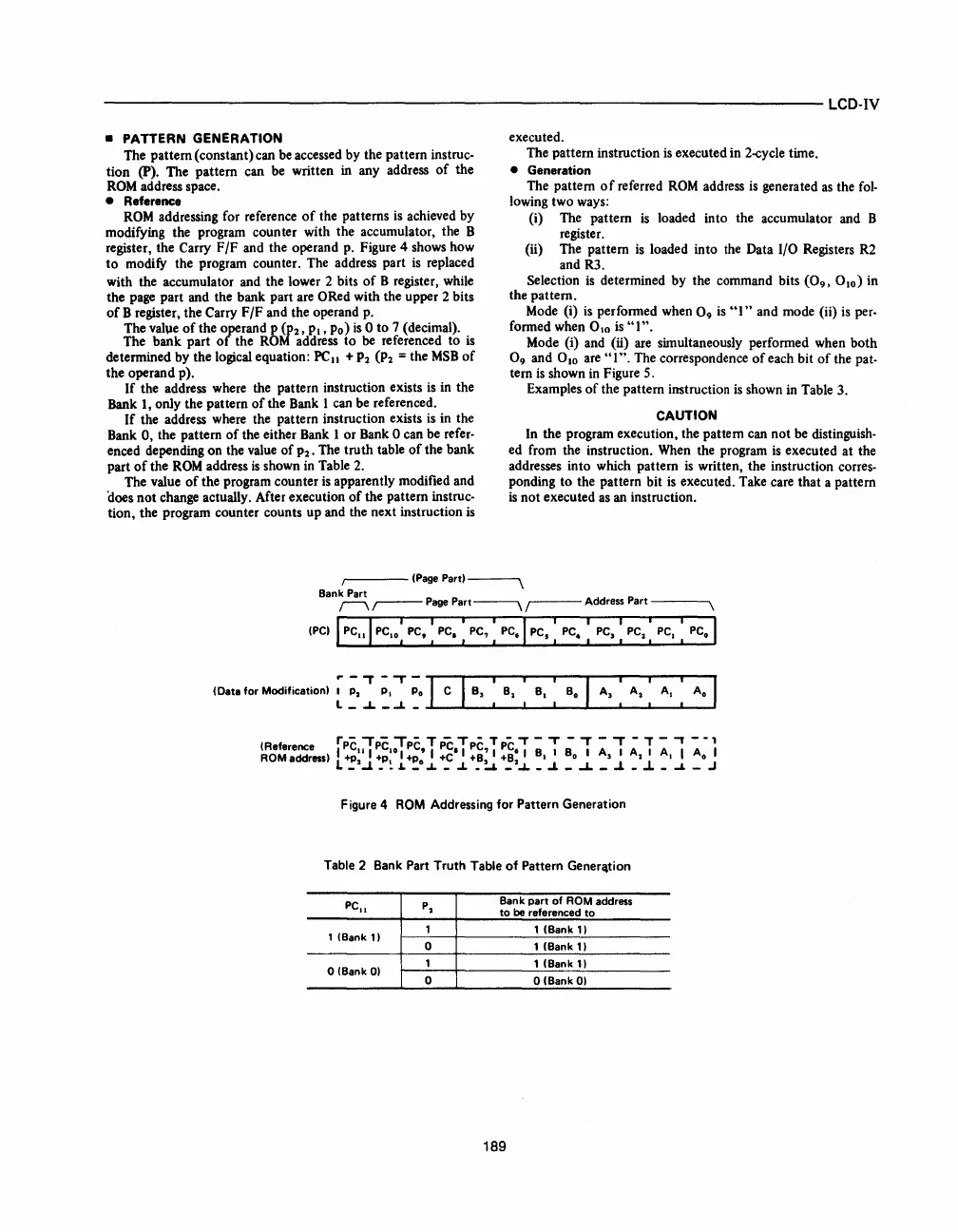
Figure 4 shows how
to
modify the program counter. The address part
is
replaced
with the accumulator and the lower 2 bits
of
B register, while
the page part and the bank part are
ORed with the upper 2 bits
of
B register, the Carry F/F and the operand
p.
The vahle
of
the operand p (P2,
PI,
Po)
is
0 to 7 (decimal).
The bank part
of
the
ROM
address to be referenced to
is
determined by the logical equation:
PC
II
+
P2
(P2
= the
MSB
of
the operand p).
If
the address where the pattern instruction exists
is
in the
Bank
1,
only the pattern
of
the Bank I can be referenced.
If
the address where the pattern instruction exists
is
in the
Bank
0,
the pattern
of
the either Bank I or Bank 0 can be refer-
enced depending on the value
of
P2. The truth table
of
the bank
part
of
the
ROM
address
is
shown in Table
2.
The value
of
the program counter
is
apparently modified and
'does not change actually. After execution
of
the pattern instruc-
tion, the program counter counts up and the next instruction
is
executed .
The pattern instruction
is
executed in 2-cycle time.
• Generation
The pattern
of
referred
ROM
address
is
generated
as
the
fol-
lowing two ways:
(i)
The pattern
is
loaded into the accumulator and B
register.
(ii)
The pattern
is
loaded into the Data I/O Registers
R2
and R3.
Selection
is
determined by the command bits
(0
9
,
0
10
) in
the pattern.
Mode
(i)
is
performed when 0
9
is
"I"
and mode (ii)
is
per-
formed when 0
10
is
"I".
Mode (i) and
(ii)
are simultaneously performed when both
0
9
and 010
are"
I
".
The correspondence
of
each bit
of
the pat-
tern
is
shown
in
Figure 5.
Examples
of
the pattern instruction
is
shown in Table 3.
CAUTION
In the program execution, the pattern can not be distinguish-
ed from the instruction.
When
the program
is
executed at the
addresses into which pattern
is
written, the instruction corres-
ponding to the pattern bit
is
executed. Take care that a pattern
is
not executed
as
an instruction.
I
(PagePartl~
Bank Part
r--'\
~
Page
Part~
r-
Address Part
----,
Figure 4
ROM
Addressing for
Pattern
Generation
Table 2 Bank
Part
Truth
Table
of
Pattern Gener"tion
PC"
P
2
Bank
part
of
ROM address
to
be
referenced
to
1 (Bank
11
1 1 (Bank
11
0 1 (Bank
11
o (Bank
01
1
1 (Bank
11
0 o (Bank
01
189


 To Next Page
 Loading...


